
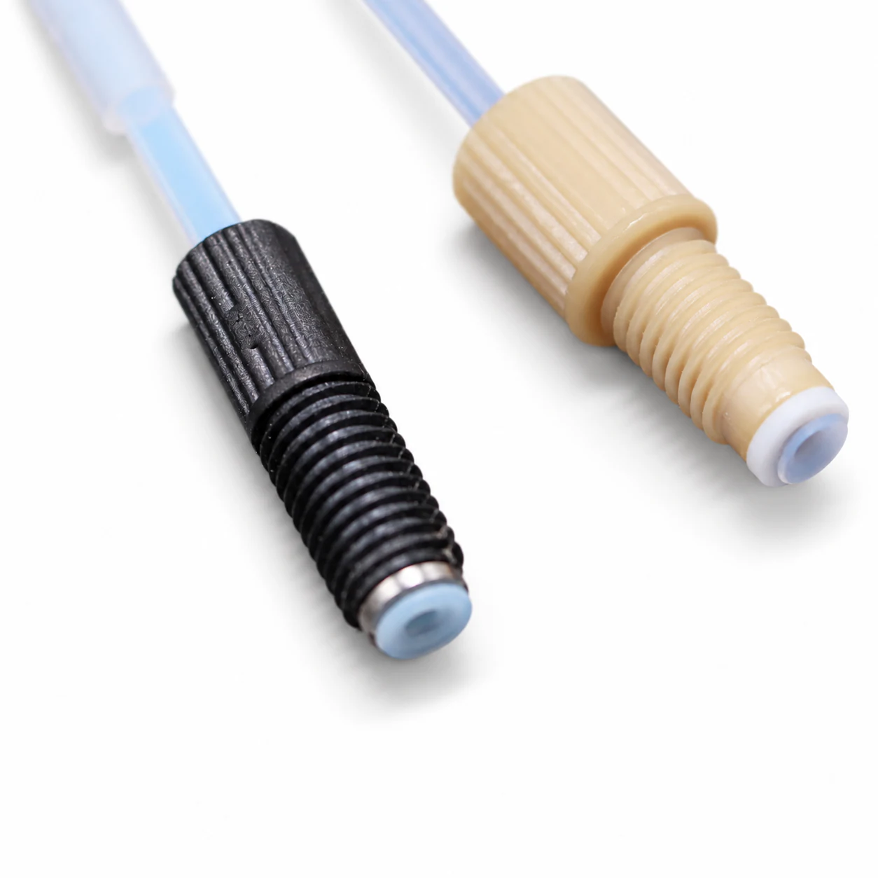
Flanged Tubing Assemblies
FOREACH supplies single- and double-flanged tubing assemblies for flat-bottom fluid ports in in-vitro diagnostic and automated analytical instruments. The flanged tube end, matching fitting and washer form a face seal. Equipment development, assembly to drawing and batch production are supported.
Select FEP, PTFE or PFA tubing to suit the flanging process and mating port. PPS, PVDF and PEEK fittings are available in standard and compact structures, with M6×1 and 1/4-28 UNF threads; selected miniature configurations support 6-40 UNF. Tube OD options are 1.6, 2.0, 2.5, 3.0 and 3.2 mm, with FEP IDs spanning 0.3–2.0 mm in specified ID/OD pairs. SUS, PEEK or PTFE washers are selected by model. Length, A/B fittings, stop tubes and identification can be specified.
FOREACH holds ISO 9001 and ISO 13485 quality management system certifications.
Typical Applications:
Reagent line connections, Cleaning-fluid line connections, Internal instrument fluid connections, Custom fluid-path assembly
Assembly Parameters
| Tubing material and appearance | Transparent FEP, natural PTFE, PFA, black PTFE |
|---|---|
| Tube ends | Single- or double-flanged ends |
| Fitting structure | Standard, compact |
| Fitting material | PPS、PVDF、PEEK |
| Standard threads | M6×1、1/4-28 UNF |
| Support washers | Material and size matched to the fitting model |
| Finished length | Custom to drawing, with specified length and tolerance |
| A/B ends | Fitting material, thread and connection type can be specified separately |
| Optional configurations | Stop tubes, heat-shrink labels |
Tube Size Combinations
| Material / Tube OD (mm) | Matching Tube ID (mm) |
|---|---|
| Transparent FEP · 1.6 | 0.3 / 0.5 / 0.8 / 1.0 |
| Transparent FEP · 2.0 | 1.0 |
| Transparent FEP · 2.5 | 1.5 |
| Transparent FEP · 3.0 | 2.0 |
| Transparent FEP · 3.2 | 1.6 |
| Natural PTFE · 1.6 | 0.5 / 0.8 / 1.0 |
| Natural PTFE · 2.0 | 1.0 / 1.2 |
| Natural PTFE · 2.5 | 1.5 / 1.7 |
| Natural PTFE · 3.0 | 2.0 |
| Natural PTFE · 3.2 | 1.6 |
| PFA · 1.6 | 0.5 / 0.8 / 1.0 |
| Black PTFE · 1.6 | 0.8 |
| Black PTFE · 2.0 | 1.0 |
| Black PTFE · 2.5 | 1.5 |
| Black PTFE · 3.0 | 2.0 |
| Black PTFE · 3.2 | 1.6 |
These are available tubing sizes. Confirm flange dimensions and mating ports against the assembly drawing.
Match fitting material, structure and thread to the corresponding model.
Miniature option: 6-40 UNF, PEEK fitting, 1.6 mm tube OD. Confirm the complete end configuration against the selected model.
Working pressure and temperature must be confirmed for the specific assembly configuration.
Flanged Tubing Applications & Customization
Equipment development, assembly to drawing, sample development and batch production are supported.
Instrument fluid-path integration
Assemblies for in-vitro diagnostic and automated analytical instruments are selected against the actual reagent, cleaning fluid and connection requirements.
Tubing configuration
Select material, dimensions, length and end connections for the installation.
Assembly drawings and dimensions
Provide tube ID/OD, finished length and tolerance, length measurement datum, A/B port drawings, fitting materials, threads and installation space. Show stop and label positions and dimensions on the assembly drawing.
Fluids, pressure and temperature
Specify the working fluid, concentration, cleaning fluid, contact time, pressure, temperature and inspection requirements to confirm wetted materials and the complete assembly.
Installation and mating ports
Check the flange face, washer orientation and port sealing face. Even when threads match, verify port depth and flange dimensions.
Quality documents and delivery
FOREACH holds ISO 9001 and ISO 13485 quality management system certifications. Applicable REACH and RoHS reports and material safety data sheets (MSDS) can be supplied for relevant connection components according to material and model. Dimensional inspection, seal testing, identification and packaging requirements for samples and batches are agreed for each project.
Submit your requirements
Prepare an assembly drawing, port drawing or BOM, together with sample quantity, batch requirements and acceptance criteria.
Use the fluid resistance calculator for preliminary estimates when comparing how tube diameter or length affects pressure drop.
Estimate fluid resistanceNo 2D Drawing
Frequently Asked Questions
Specify flanging at one or both ends, and define the fitting material, thread and connection type for A/B separately. For a single-flanged assembly, specify the other end connection on the drawing.
Submit your requirements
Prepare an assembly drawing, port drawing or BOM, together with sample quantity, batch requirements and acceptance criteria.