
Choosing a 100, 250 or 500 μL Piston Pump for Clinical Chemistry Dosing
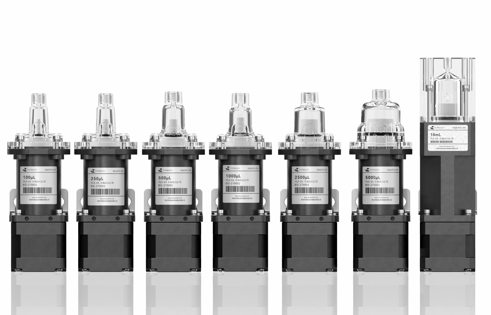
Start a clinical chemistry piston-pump selection by identifying the fluidic task: direct reagent dispensing, sample metering, diluent addition or system-liquid actuation of a sampling tip. The 100, 250 and 500 μL values describe nominal pump capacities. The decision depends on the volume actually delivered per dose, the number of doses required after one aspiration and the time available for the complete sequence.
1. Turn the dosing task into explicit inputs
When reagent passes through the pump chamber, compatibility must cover the head, piston, seals and valves. When system liquid actuates a sample at the tip, the liquid interface, residual sample and complete transfer also need attention. Similar commanded volumes can therefore require different wetted paths and verification methods.
| Input | What to specify | Decision it supports |
|---|---|---|
| Dose volumes | Minimum, typical and maximum delivered volume, in μL | Operating stroke range and test points |
| Dispensing sequence | Doses after each aspiration; equal or variable volumes | Capacity budget and aspiration count |
| Time window | Aspiration, valve switching, dispensing, settling and refilling | Complete cycle feasibility |
| Fluid path | Liquid composition, temperature, levels, backpressure, valves and tip | Materials and actual delivery |
| Integration | Capacity-specific CAD, interfaces, cables and drive requirements | Series and configuration selection |
Complete the task definition before ranking capacities. An industry name does not define a pump size, and different metering channels in one instrument need not use the same capacity.
2. A 20 μL command uses different fractions of the stroke
Stroke utilization ≈ commanded dose volume / corresponding full-stroke capacityAn initial comparison for approximately linear displacement and volume, with consistent command and usable-stroke definitions. This is not a prediction of delivered-volume accuracy.| Hypothetical 20 μL command | 100 μL capacity | 250 μL capacity | 500 μL capacity |
|---|---|---|---|
| Nominal stroke utilization | 20% | 8% | 4% |
| Verification focus | Actual 20 μL delivery and cycle time | Small-stroke delivery and repeated dispensing | Smaller-stroke delivery, refill benefit and space |
The percentages describe motion range only. They do not prove that the 100 μL pump is more accurate, or justify transferring a full-stroke accuracy specification to a 4% stroke. Transmission behavior, valve timing, bubbles, tubing compliance, aspiration and dispense speed, and the delivery tip all matter. Command resolution and nominal volume per step do not establish a minimum reliable dose.
3. Include repeated doses and reserved volume in the budget
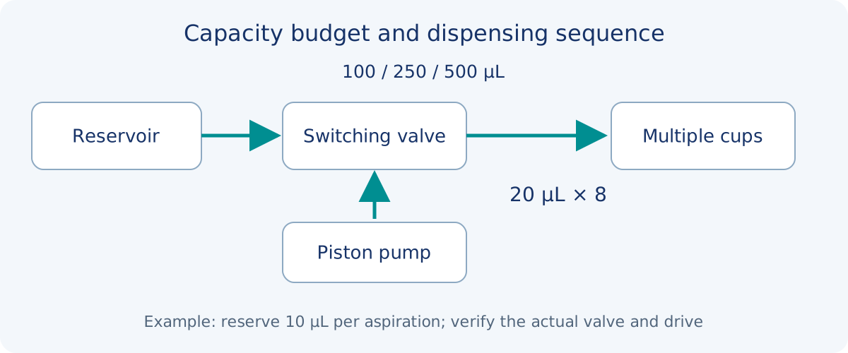
n = floor((Vusable − Vreserve) / Vdose)For equal doses, n is an initial estimate of complete dispenses per aspiration. Vusable is the confirmed available aspirated volume, Vreserve is the process reserve and Vdose is the commanded dose. Vusable must be at least Vreserve, and Vdose must be positive.| Candidate capacity | Complete doses per aspiration | Aspirations for eight cups | Refills after the initial aspiration |
|---|---|---|---|
| 100 μL | 4 | 2 | 1 |
| 250 μL | 12 | 1 | 0 |
| 500 μL | 24 | 1 | 0 |
Both 250 and 500 μL meet the assumed eight-cup budget without a further refill. Increasing capacity beyond that point does not reduce refills in this batch. Compare actual dose performance, space and liquid-change requirements next. Recalculate individual commands if usable volume or dose sizes differ.
4. Compare the complete sequence, not dispense speed alone
Tbatch = Σ(Taspiration + Tvalve + Tdispense + Tsettling + Tmotion and other required actions)Count each action as it actually occurs. Where actions overlap, determine the critical path from the control sequence instead of adding overlapping times twice.Avoiding a refill saves time only when that refill constrains the critical path. An instrument that aspirates while another mechanism moves differs from one that stops dosing to refill. A larger pump may also change aspiration travel, fluidic connections and installation constraints.
- Keep batch size, doses and liquid constant and retain the complete command log.
- Separate the first dispense, the first dispense after refill, intermediate dispenses and the last dispense.
- Check delivered volume before ranking cycle time.
- When increasing speed, examine bubbles, valve response and the end of delivery. Motor-command completion does not establish complete delivery into the cup.
5. Compare the actual EA, SM and TM configurations
Foreach series information includes 100, 250 and 500 μL capacity options within EA, SM and TM. Check series positioning separately from the capabilities of an individual configuration. Equal nominal capacity does not establish matching dimensions, materials, interfaces, drive requirements or performance conditions.
| Series | Main comparison at this stage | Information to confirm |
|---|---|---|
| EA precision piston pump | Matching a broad-capacity platform to the channel task | Capacity-specific drawing, materials, interface and control |
| SM miniature piston pump | Pump, valve, tubing and cable placement in a compact instrument | Complete installation envelope and performance at working dose |
| TM ultra-compact piston pump | Integration where space is more restricted | Model drawing; displayed acrylic (PMMA) head and ceramic piston, with other configurations reviewed separately |
EA and SM series information includes 1/4-28 UNF or M6 fluidic interfaces; displayed TM configurations use 6-40 UNF. Confirm the actual drawing and allow for fitting projection, tubing bends and maintenance. EA full-stroke metrics, SM repeatability information and TM configuration-specific validation must not be combined into one promise for all three series.
6. Verify the working doses, not just the full stroke
Cover the minimum, typical and maximum doses actually used, together with operating states that can change delivery. Choose repetition counts and acceptance criteria for the instrument requirement and verification purpose; a generic article cannot replace the project acceptance plan.
| Record group | What to retain |
|---|---|
| Sample and circuit | Model, configuration, sample ID, valve, tip, tubing, liquid levels and backpressure |
| Liquid and measurement | Actual medium, temperature, density, instrument, method and uncertainty |
| Command conditions | Dose or steps, speeds, valve timing, settling and standby duration |
| Raw results | Individual masses or volumes, first-dose/refill/steady-state labels and anomalies |
| Acceptance | Accuracy, repeatability, delivery time, tip behavior and the basis for each criterion |
Gravimetric testing requires density at the relevant liquid temperature and control of evaporation, retained droplets and transfer losses. A formal procedure must also evaluate effects such as buoyancy corrections and measurement uncertainty. Dividing a mass reading by density is not, by itself, a complete calibration procedure.
7. Record a reasoned selection
State the dose and timing requirements, why the capacity was retained, why the series and materials were chosen, what conditions were tested and what remains unverified. For the arithmetic task above, 250 μL is one candidate for reducing refills. That is not a final recommendation for a real clinical chemistry instrument.
Frequently asked questions
Why not always choose 500 μL?
If 250 μL already covers the required repeated doses, 500 μL may not remove another refill. Compare actual small-dose performance, timing, installation and liquid-change requirements.
Does a 100 μL pump dispense only 100 μL at a time?
No. Nominal capacity and dose volume are different. The usable dose range depends on commands, effective stroke and actual delivery verification.
Can the example 10 μL reserve be used in firmware?
Not without verification. It is an illustrative budget value, not a product requirement. Priming, usable stroke, valve paths and dispensing strategy determine the real reserve.
Are equal-capacity EA, SM and TM pumps interchangeable?
Capacity alone cannot establish interchangeability. Verify drawings, interfaces, materials, valve and drive arrangements, and performance at the actual dose and timing.
What can be done before actual reagent testing?
Use formal specifications and clearly stated calculations to shortlist candidates and prepare the test circuit. Actual medium compatibility and delivered-volume performance still require verification.