
Acceleration and Deceleration Curves for Piston-Pump Drives
A stepper motor cannot jump from standstill to any target speed under any load. A piston-pump drive must overcome mechanical friction, hydraulic load and moving inertia at startup, then reserve travel for controlled deceleration. A motion profile changes pulse frequency progressively so the motor can enter and leave its operating speed reliably.
1. Why piston pumps need acceleration control
Select the profile against the motor torque-speed curve at the actual drive voltage, current and microstep setting. Holding torque alone does not describe available high-speed running torque.
2. Separate missed steps from vibration
Excessive acceleration can demand more torque than the motor can produce at that speed, causing missed steps. Load, supply, current setting, resonance and assembly also matter. Low acceleration is not itself a missed-step cause, although moving slowly through a resonance band can prolong vibration.
For pulse frequency, load torque and transmission ratio, see Precision Piston Pump Stepper Motor Calculation and Selection.
3. Linear, S-curve and parabolic profiles
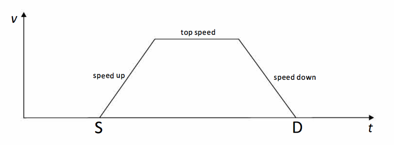
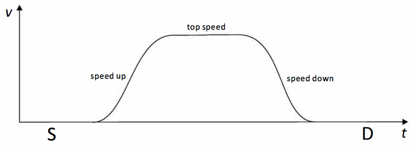
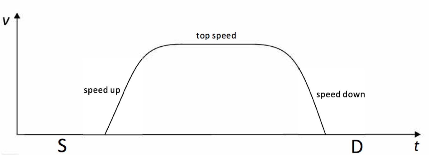
A linear velocity ramp uses constant acceleration but changes acceleration abruptly at transitions. An S-curve changes acceleration progressively to reduce shock. A parabolic profile is another nonlinear plan whose parameters redistribute acceleration across speed ranges.
The diagrams explain profile shapes; they are not operating parameters for a specific pump.
4. Convert motor speed to piston speed and theoretical flow
For a motor directly driving a lead screw, let lead p be in mm/rev and speed n in rev/s. Piston speed is v = p × n. With effective piston area A in mm², theoretical flow is Q = A × v in mm³/s, and 1 mm³ = 1 μL. Include any transmission ratio.
v = p × n; Q = A × vA motion-planning relation only. Backpressure, resistance, bubbles, valve timing and seals affect delivered liquid.For reversal lost motion, see Precision Piston Pump Backlash Compensation.
5. Commissioning sequence for a piston-pump program
- Verify mechanics: At low speed, confirm homing direction, limits and usable stroke.
- Tune under real load: Increase aspiration and dispense speeds gradually with the actual fluid, tubing and backpressure; the two directions need not use identical speeds.
- Record motion and valve timing: Capture start and target frequency, ramp time, microsteps, valve delay and settling time. Short strokes may never reach peak speed.
- Validate the fluid result: Measure dose, repeatability, bubbles, vibration and motor temperature. Correct mechanics alone is not final acceptance.
Conclusion
Choose the profile from the actual motor, driver, load, stroke and fluidic timing. Validate both motion integrity and delivered liquid at the shortest and most demanding operating cycles.