
How to Select a Miniature Diaphragm Pump for Life-Science Instruments: DPL60 Washing, Drainage and Waste-Fluid Guide
Life-science instruments need more than accurate sample dispensing: they also wash reaction chambers, flush tubing, remove waste, prime lines and circulate liquid. Reliable diaphragm-pump selection depends on complete fluid-path resistance, suction conditions, wetted materials and long-term duty rather than catalog maximum flow alone.
Nucleic-acid extraction systems, immunoassay analyzers, cell-analysis platforms and laboratory automation equipment often combine precise metering with rapid fluid transfer. While piston or syringe pumps meter volume, miniature liquid diaphragm pumps commonly handle washing, flushing, draining, priming and circulation.
Using the FOREACH DPL60 as an example, this guide explains how to evaluate a 600 mL/min-class pump against the actual instrument task, operating point, self-priming conditions, gas-liquid behavior, material compatibility, service life and mechanical integration.
1. Define what the diaphragm pump must do inside the instrument
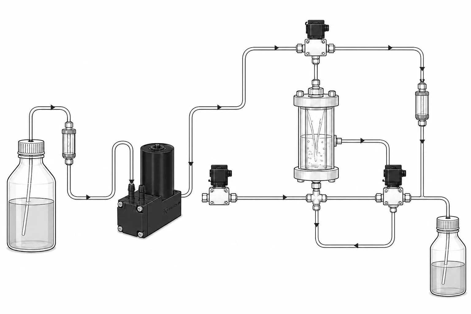
Before choosing a pump, specify its responsibility in the instrument workflow. Typical duties include:
- Draw cleaning solution or buffer from a reservoir and deliver it to downstream modules.
- Flush reaction chambers, flow cells, probes, tubing or valve manifolds to reduce liquid-exchange time.
- Drain fluid into a waste container while limiting residual liquid and cross-contamination.
- Prime long lines and remove trapped air during startup, bottle replacement or maintenance.
- Circulate compatible buffer, cleaning fluid or temperature-control liquid within the validated operating range.
2. Why start with a 600 mL/min-class DPL60 diaphragm pump?
When washing and drainage must finish within a limited cycle time, the DPL60 provides a useful starting point for comparing flow class, pressure capability, package size, electrical power, noise and service life. Its catalog values must still be interpreted within the complete fluid path.
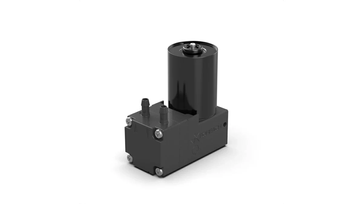
| Selection item | Representative DPL60 brushless specification | Engineering interpretation |
|---|---|---|
| Pump type | Liquid diaphragm pump | Suitable for transfer, flushing, drainage, priming and circulation |
| Rated voltage | 24 V DC ±10%; a 12 V DC ±10% version is also available | Match the instrument power supply and control method |
| Rated power | ≤8.4 W | Check power capacity, wiring voltage drop and thermal dissipation |
| Free-flow rate | 600 mL/min | Low-resistance reference flow, not a guaranteed installed flow |
| Rated pressure | 100 kPa | Pressure capability limit; do not combine it with free flow as a single operating point |
| Self-priming lift | 3 mH₂O | Retest at the lowest liquid level, longest suction line and dry-start condition |
| Tubing connection | Compatible with 3.2 mm inside-diameter tubing | Also verify tube length, bends and the minimum bore of fittings and valves |
| Representative wetted materials | PPS pump head; EPDM or PTFE diaphragm; EPDM or FFKM check valve | Validate every wetted component for the actual fluid, temperature and exposure time |
| Reference service life | 10,000 h for the brushless version | Applies under specified voltage, fluid, load and duty-cycle conditions |
These values define an initial selection window, not an equipment-level performance guarantee. Fluid properties, pressure, temperature, installation orientation, switching strategy and manufacturing variation can all alter actual results.
3. Do not assume 600 mL/min is the installed flow rate
A 600 mL/min rating normally describes free flow under specified low-load conditions. In an instrument, suction tubing, valves, fittings, filters, flow cells, elevation changes and waste-side back pressure create system resistance; actual flow occurs where the pump curve intersects the system curve.
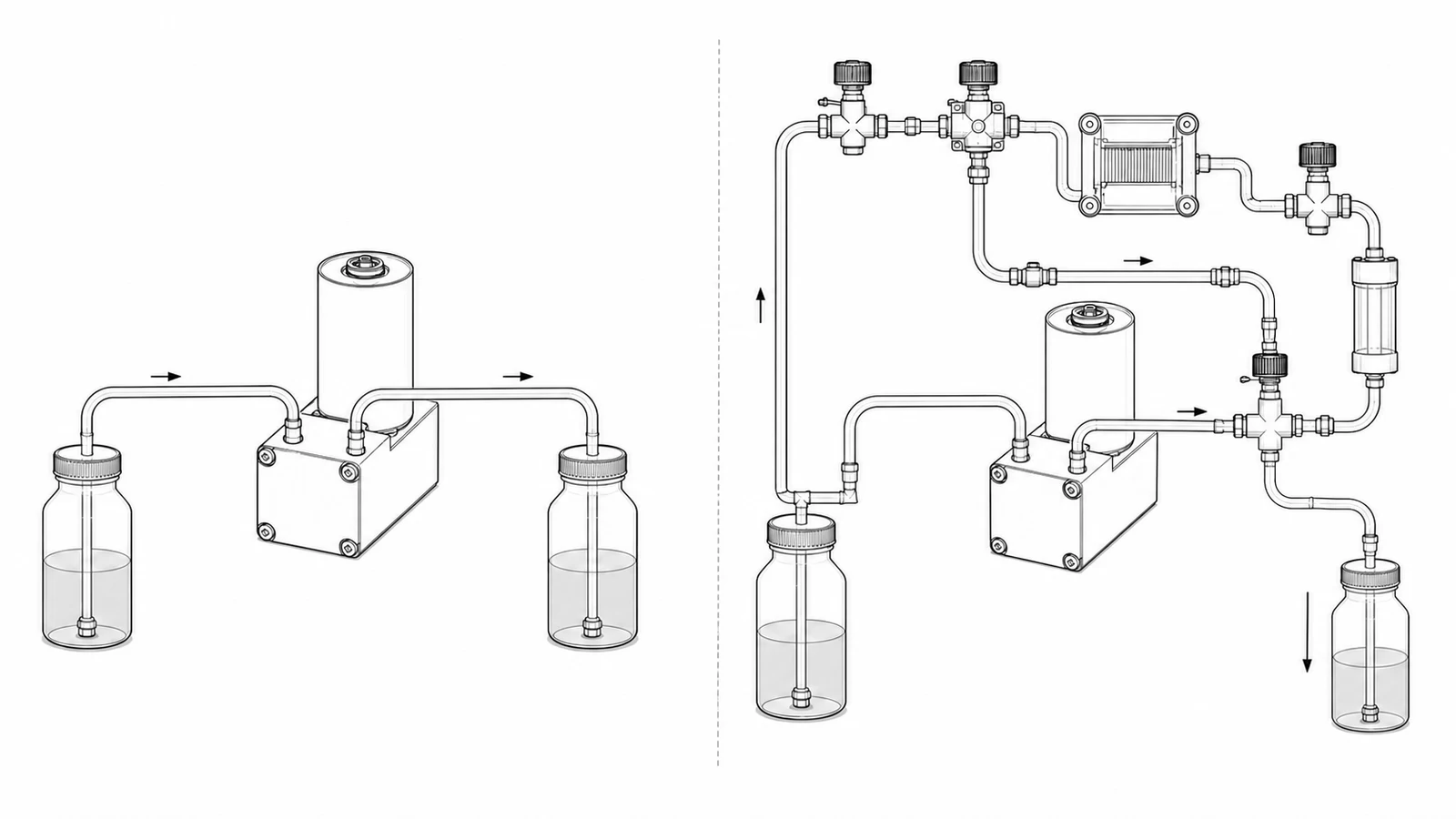
Specify the required effective flow and measure or estimate inlet vacuum and outlet back pressure. If filters are present, test a new filter, a partially loaded filter and the resistance near its replacement point.
4. Evaluate self-priming together with bottle position and dry-line startup
Self-priming lift is not independent of the suction circuit. Reservoir elevation, tube inside diameter, length, bends, reduced-bore fittings, trapped air and pump position all affect dry-start and repriming time.
- Measure the real elevation difference from the lowest permissible fluid level to the pump inlet.
- Test with the final tube diameter, length, bend radius and fitting combination.
- Check high points for trapped air and inspect suction lines for pinching or kinks.
- Cover the first dry startup, bottle replacement and repriming after maintenance.
- Record the time until stable liquid delivery rather than checking only whether priming eventually succeeds.
5. Waste drainage transitions from liquid to a gas-liquid mixture and then air
A waste line is not always completely full. Toward the end of drainage, bubbles may appear, followed by gas-liquid mixture and eventually mostly air. These states change flow, noise, pulsation, temperature rise and check-valve response.
Validate with the actual waste fluid, foam content and drain sequence. If the main duty becomes sustained gas-liquid extraction rather than liquid transfer, evaluate a purpose-designed gas-liquid diaphragm pump instead of relying only on DPL60 liquid specifications.
6. Material compatibility requires more than one PTFE component
Fluid contacts the pump head, diaphragm, check valves, tubing, fittings and seals. One PTFE part does not make the entire wetted path compatible. Published DPL60 performance uses purified water as a reference; buffers, detergents, disinfectants and surfactant-containing fluids require separate validation.
- Exact fluid name, formulation or principal ingredients.
- Operating concentration and minimum/maximum temperature.
- Single exposure duration, daily cycle count and accumulated operating time.
- Different fluids used during cleaning, disinfection or idle soaking.
- Acceptable swelling, leaching, adsorption, permeation and particle-generation risks.
7. Consider motor life, duty cycle and maintenance intervals
Pump life cannot be inferred solely from the instrument's calendar life. Accumulated operating hours, switching events, back pressure, current, temperature, fluid and dry-running time affect the motor, bearings, diaphragm and valves.
The DPL60 brushed version commonly has a reference life of 3,000 h, while the brushless version commonly has 10,000 h under specified conditions. Continuous operation, frequent cycling and high back pressure can produce different life distributions even at the same accumulated hours.
Related engineering guide:How long can a miniature diaphragm pump run continuously?.
8. Account for pulsation, tubing compliance and valve response
Diaphragm pumps deliver periodic flow. Tubing elasticity, internal volume, check-valve dynamics and downstream chambers modify pressure ripple and instantaneous flow. Average flow may dominate washing time, while sensitive flow cells, sensors or spray patterns also require pulsation assessment.
Choose a buffer volume, damper or alternative tubing only when downstream sensitivity and measured results justify it. Additional volume can increase fluid-exchange time and residual liquid.
9. Verify mounting and noise in the complete instrument structure
The same pump can sound different when installed on sheet metal, a plastic bracket or a closed enclosure. Mounting stiffness, vibration isolation, tubing loads, enclosure resonance, entrained air and back pressure all change perceived noise and vibration transfer.
- Test the final mounting orientation and attachment points without imposing side loads on pump ports.
- Check tubing bend radius, connection stress and high-point air accumulation.
- Record noise during dry priming, stable liquid transfer, gas-liquid flow and final drainage.
- Close the instrument enclosure and inspect interactions among pump, bracket, wiring harness and tubing.
10. When is the DPL60 no longer the best candidate?
The DPL60 is not a universal answer for every life-science fluid path. Change the candidate pump when the controlling system constraint changes.
| Fluid-system requirement | Candidate to evaluate | Selection reasoning |
|---|---|---|
| Routine washing, flushing, drainage or circulation with fast liquid exchange | DPL60 | Start from the 600 mL/min free-flow class and validate the actual operating point |
| Lower flow with tighter size and electrical-power limits | DPL30 | A lower flow class can reduce oversupply and package size |
| High resistance from narrow tubing, needles, filters or pressurized chambers | DPL30H | Check remaining effective flow at the required operating pressure |
| Sustained gas-liquid mixture, waste aspiration or higher flow demand | DPGL800 or another gas-liquid pump | Select according to actual gas fraction, evacuation state and task profile |
11. Complete at least six prototype validation groups
- Operating-point validation: use final tubing, valves, filters, chambers and elevation; record inlet pressure, outlet pressure, flow, voltage and current.
- Self-priming validation: cover the lowest reservoir level, longest suction line, first dry startup, bottle changes and post-maintenance repriming.
- Bubble and drainage validation: observe startup bubbles, gas-liquid flow, end-of-drain behavior, residual volume, noise and recovery time.
- Fluid compatibility validation: soak and circulate actual buffers, detergents and disinfectants, then repeat performance and visual checks.
- Duty-cycle and lifetime validation: reproduce actual start-stop timing, back pressure, temperature and daily runtime; define failure criteria before testing.
- Mechanical integration validation: inspect noise, temperature rise, resonance, tubing stress and assembly interference in the final mounting, enclosure and wiring configuration.
Conclusion: draw the complete fluid path before selecting the DPL60
Selecting a miniature diaphragm pump for a life-science instrument requires more than comparing catalog maximum flow. Define washing, drainage, waste, priming or circulation duties first, then validate fluid, tubing, valves, filters, elevation, back pressure, duty cycle and installation together.
A DPL60-class 600 mL/min miniature liquid diaphragm pump is a useful starting point for washing and drainage. If prototype results identify low-flow packaging, high back pressure or sustained gas-liquid handling as the dominant constraint, switch to a more suitable pump architecture.
FAQ: selecting a DPL60 diaphragm pump for life-science instruments
Will an installed DPL60 always deliver its nominal 600 mL/min?
No. The rating represents low-resistance free flow; inlet vacuum, outlet back pressure, valves, filters, flow cells, tubing and elevation determine the actual installed operating point.
Is the DPL60 suitable for high-accuracy sample dispensing?
It is primarily suited to washing, flushing, drainage, priming and circulation. Evaluate a piston or syringe pump when precise metered volume is essential.
Can a 3 mH₂O self-priming rating be used as a guaranteed 3 m design lift?
No. Validate the real priming time at the lowest fluid level, with the final suction tubing, fittings and valves, during dry startup and bottle replacement.
Can the DPL60 transfer every buffer, detergent and disinfectant?
No. Validate all wetted pump components, tubing, fittings and seals against actual concentration, temperature, contact duration and cleaning or soaking procedures.
Can the DPL60 handle waste containing many bubbles?
Test the actual gas fraction and drain sequence. Short end-of-drain bubbles may be manageable, but continuous gas-liquid handling may require a dedicated gas-liquid pump.
How should brushed and brushless DPL60 versions be compared?
Compare their approximately 3,000 h and 10,000 h reference lives together with accumulated runtime, switching frequency, control method, noise, maintenance interval and project cost.
Is a downstream damper or buffer volume always necessary?
No. Measure downstream pulsation sensitivity, fluid-exchange time and acceptable residual volume before adding components that increase internal volume.
What mounting orientation should be used?
Follow the official installation drawing and validate the complete instrument, avoiding port side loads, trapped air, excessively tight bends and structural resonance.
Why can changing tubing or the enclosure change pump noise?
Mounting stiffness, bracket design, tubing restraint, enclosure resonance, gas content and back pressure change vibration transmission and perceived noise.
What information should be provided for engineering selection?
Provide the fluid, concentration, temperature, required effective flow, inlet vacuum, outlet back pressure, suction lift, tubing dimensions, valves, fittings, filters, duty cycle, noise target and available installation space.