
How Long Can a Miniature Diaphragm Pump Run Continuously? A Duty-Cycle and Life Guide
A pump described as suitable for continuous operation is not a pump with unlimited life. Continuous-duty capability, accumulated service life, calendar life and statistical reliability answer different engineering questions—and all depend on the stated load, fluid, electrical drive and environment.
For an OEM instrument, the useful question is not simply whether the motor can keep turning for 24 hours. The pump must continue to start, deliver the required flow at pressure, remain within current and temperature limits, avoid leakage and meet the instrument's noise and control requirements over its real mission profile.
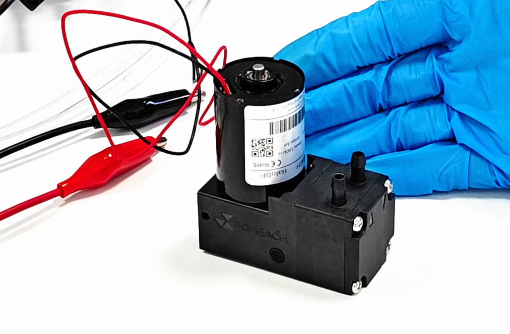
1. Continuous duty and service life are not the same specification
| Term | What it describes | What it does not prove |
|---|---|---|
| Continuous duty | The pump can operate without a scheduled rest period under defined conditions | Unlimited life or suitability at any pressure and temperature |
| Accumulated running life | Total powered operating time until a defined limit | Calendar years in a particular instrument |
| Calendar life | Elapsed time including storage and idle periods | The number of pumping cycles or starts |
| Start-stop endurance | Ability to withstand repeated start and transient events | Equivalent continuous-running hours |
| Reliability metric | Population-level result with a statistical definition | A conclusion from one successful sample |
If a pump is operated 24 hours per day, every day, 3,000 accumulated hours is about 125 days and 10,000 hours is about 417 days. If the same pump runs two hours per day, those hour totals correspond to 1,500 and 5,000 operating days. Neither conversion accounts for starts, load or environment.
2. Convert the instrument mission profile into pump demand
A mission profile records when the pump runs, how often it starts, the pressure and current in each state, fluid temperature and surrounding environment. This is the bridge between a pump life figure and the instrument's expected field use.
Ttotal = Σ(Ni × ti)Ni is the number of events in operating state i and ti is the powered duration per event. Start count and load distribution must be tracked separately.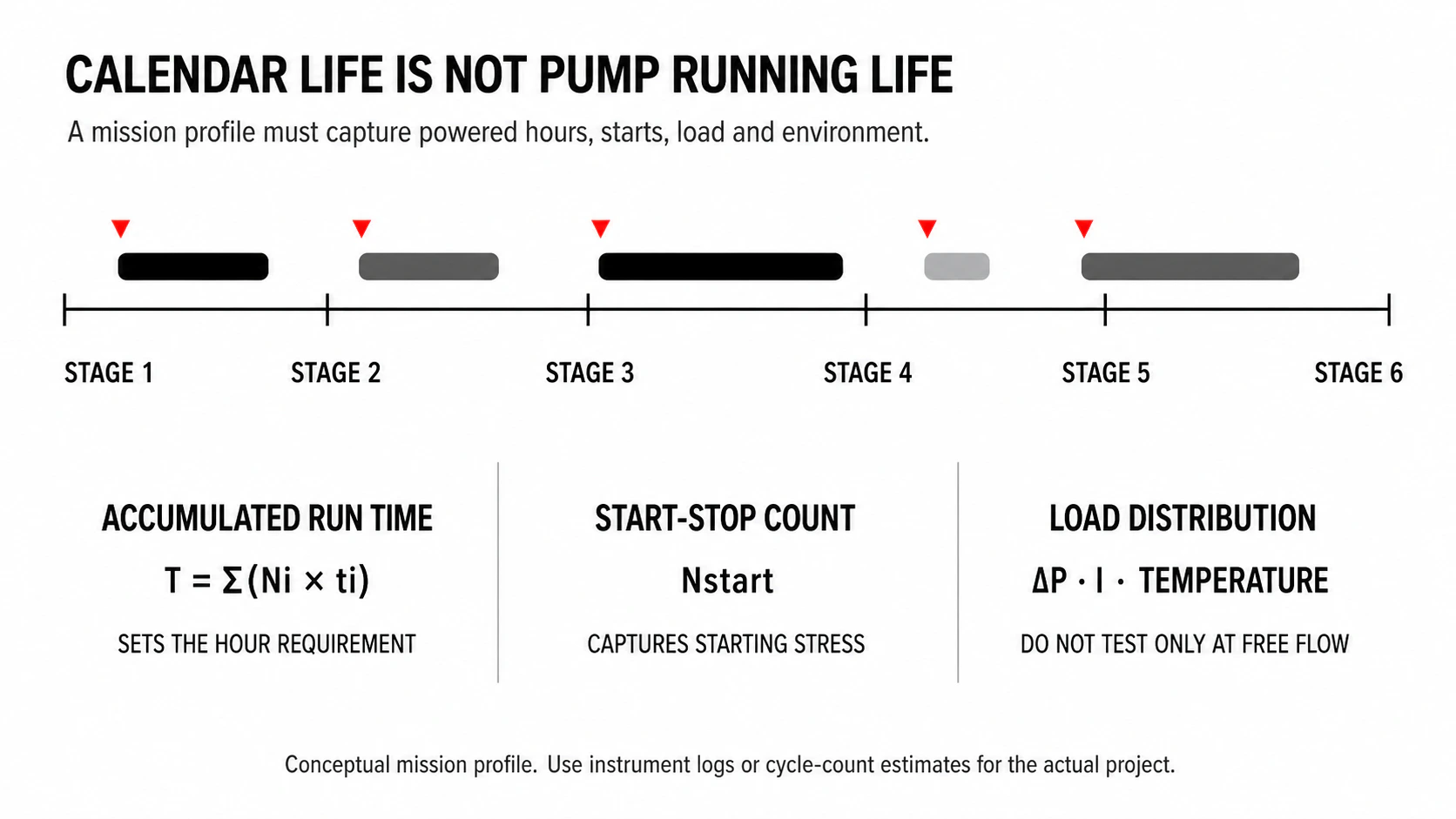
3. Why brushed and brushless versions have different life limits
A brushed DC motor transfers current through physical brush-to-commutator contact. That interface introduces sliding wear, electrical arcing, contact resistance and debris. A brushless motor commutates electronically, removing brush wear but not every possible motor, bearing, winding, controller or pump-head failure mode.
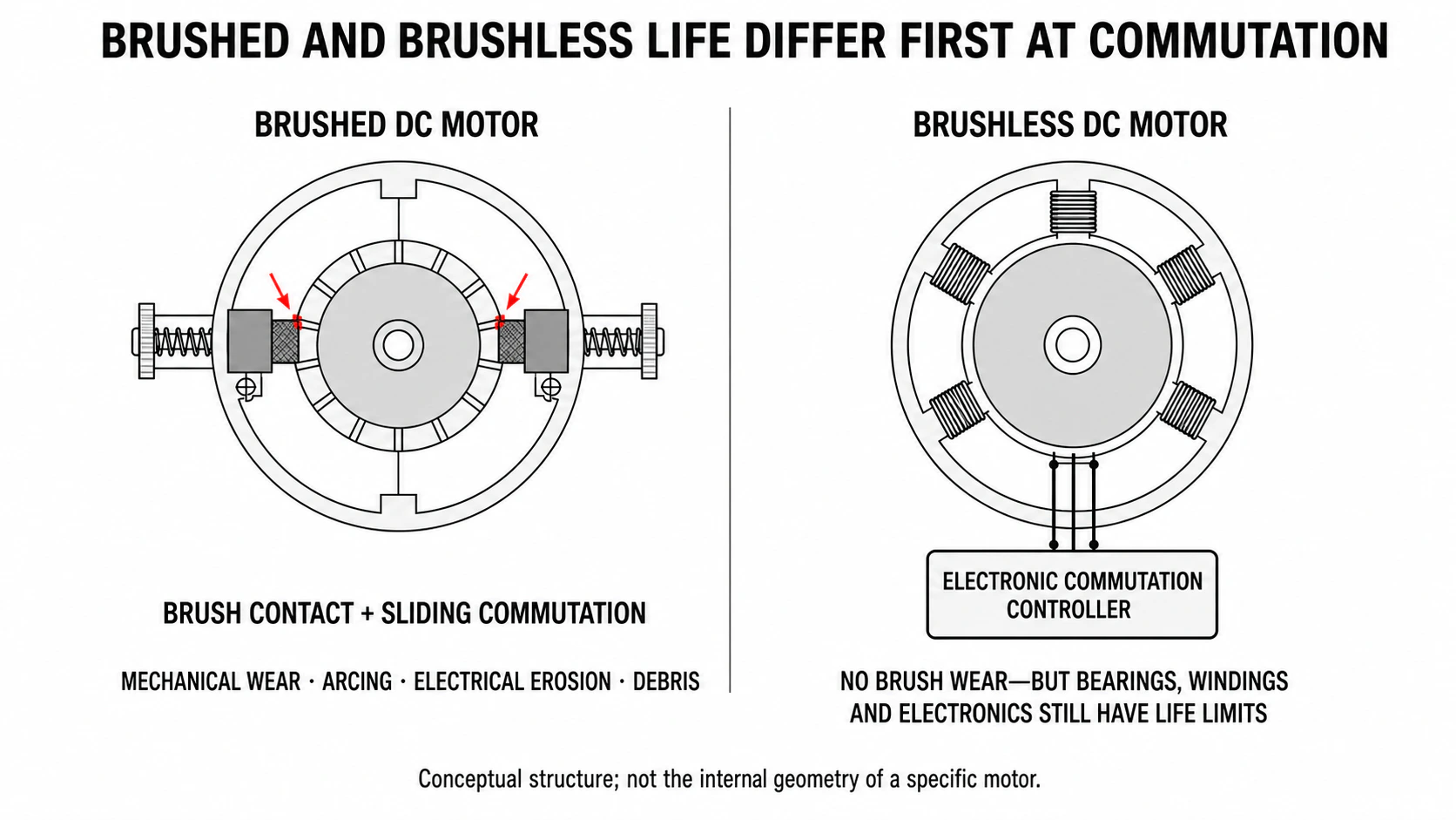
| Consideration | Brushed DC | Brushless DC |
|---|---|---|
| Commutation | Mechanical brush contact | Electronic switching |
| Common life concern | Brush and commutator wear | Bearings, winding insulation and electronics |
| Control | Simple two-wire supply is common | Speed, direction or feedback may be available by configuration |
| EMC | Brush arcing is an additional source | PWM and switching electronics still produce EMI |
| Best fit | Limited hours, simple control or cost-sensitive service | Long duty, higher control needs or costly field replacement |
4. The pump head can set the life limit too
Motor life is only one part of pump life. A higher differential pressure increases torque demand and copper loss, but it also changes diaphragm stress, check-valve dynamics and fluid temperature. Chemical exposure, particles, gas, dry running and pressure cycling can shift the dominant failure mode away from the motor.
Pcopper = I²R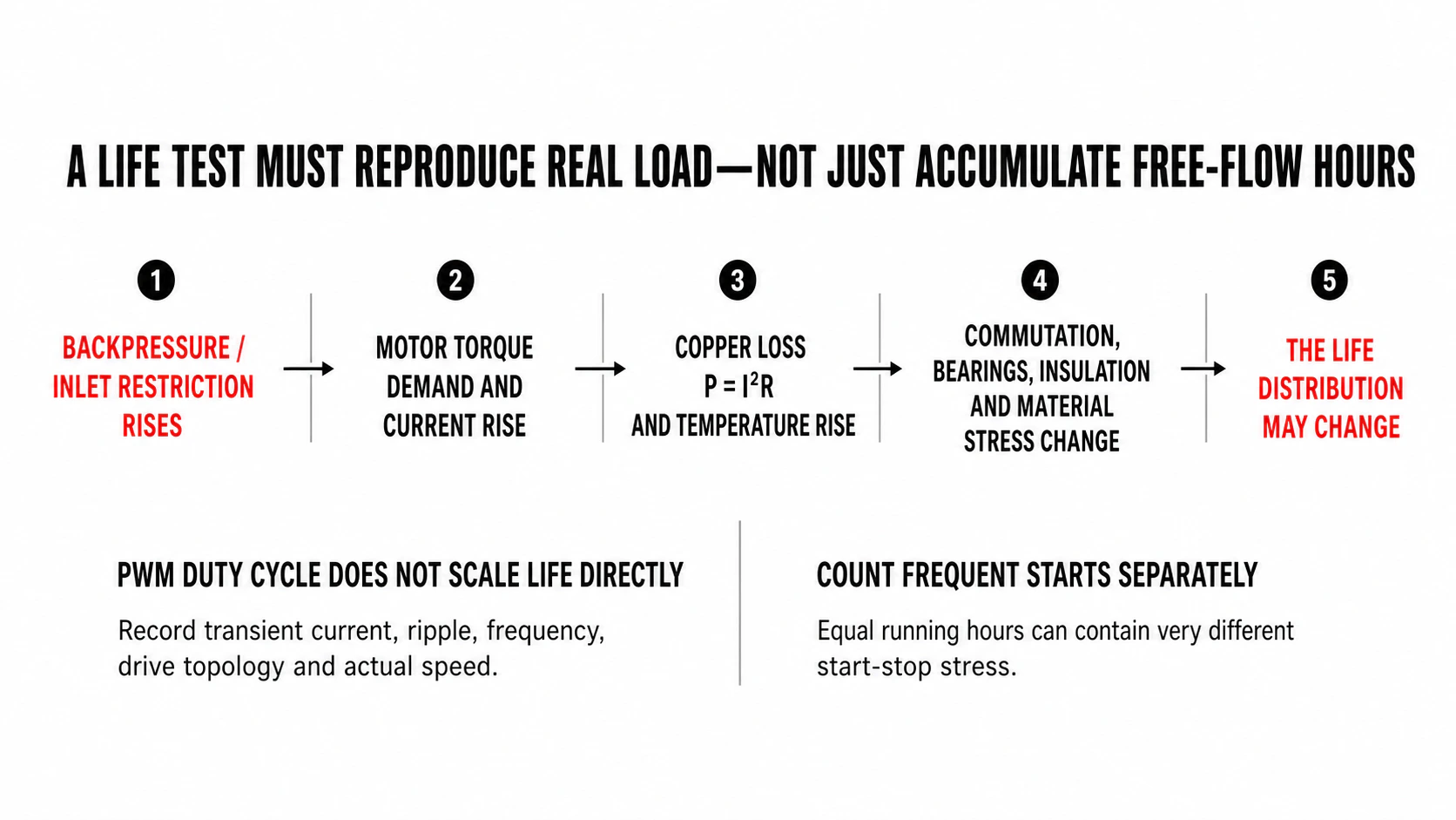
| Stress | Possible effect | Record during validation |
|---|---|---|
| Backpressure or inlet restriction | Higher load, incomplete filling or altered valve timing | Pin, Pout, current, flow and temperature |
| Start-stop cycling | Inrush, transient torque and repeated pressure events | Start count, failed starts and waveform |
| PWM control | Different current ripple, speed and commutation state | Frequency, duty, topology, current ripple and actual speed |
| Fluid and temperature | Viscosity, compatibility and material aging change | Formulation, fluid temperature and exposure time |
| Installation | Heat rejection, vibration and tubing load change | Orientation, ambient temperature and mounting |
5. Define failure before starting a durability test
A pump that still rotates may already have failed the instrument requirement. Life testing therefore needs measurable limits defined before the first sample starts.
| Failure dimension | Possible measurement | Example basis |
|---|---|---|
| Starting | Starts at specified voltage, load and temperature | Product or instrument minimum |
| Operating point | Flow, suction capability and stability at pressure | Initial degradation limit or project threshold |
| Electrical | Run current, inrush and feedback signal | Driver and motor limits |
| Mechanical | Noise, vibration, seizure and bearing condition | Repeatable detection limit |
| Fluidic integrity | Leakage, backflow, loss of prime or abnormal bubbles | Fluid, pressure and risk requirement |
| Control function | Maintains commanded state and feedback | Test-plan acceptance criteria |
6. Build a traceable durability loop
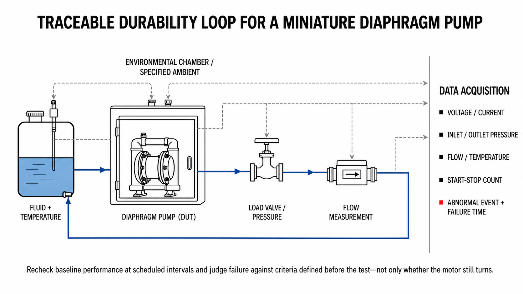
- Trace each sample by configuration, batch, motor, wetted materials and initial performance.
- Fix pump-terminal voltage, current limit, PWM and start-stop logic.
- Control fluid composition, temperature, contamination and replacement interval.
- Reproduce inlet pressure, outlet pressure, tubing, valves, filters and terminal load.
- Log voltage, current, pressure, flow, temperature, speed and abnormal states.
- Recheck startup, flow, leakage, current and noise at scheduled intervals.
- Record failure time, mode, teardown evidence and root-cause conclusion.
7. One 10,000-hour sample is not a B10 claim
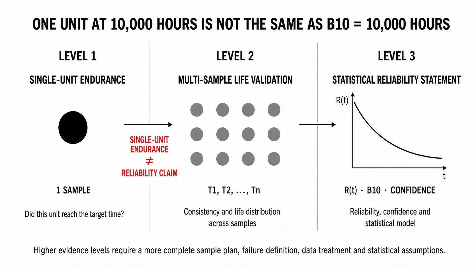
| Evidence level | Data | Supported conclusion |
|---|---|---|
| Single-unit endurance | One unit reaches a target time | That sample completed the test under the stated conditions |
| Multi-sample life validation | T1, T2, …, Tn | Consistency, early failures and a life distribution can be examined |
| Reliability statement | Failures/censoring, model and confidence | B10 or reliability can be stated within explicit statistical conditions |
R(t) = exp[-(t / η)^β]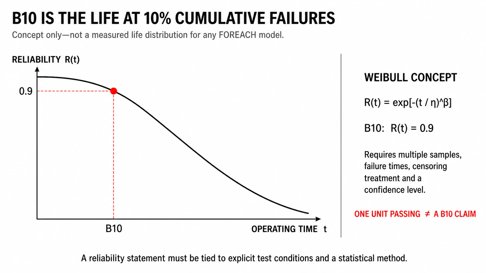
n ≥ ln(1 - C) / ln(R)For a simple zero-failure demonstration at one target time, 90% reliability at 90% one-sided confidence requires at least 22 independent units with zero failures. This does not establish a Weibull shape parameter or justify time extrapolation.8. Accelerated life is not a simple multiplication exercise
Raising temperature, pressure, speed, voltage or start frequency can introduce a new overload failure rather than accelerate the intended mechanism. Without a validated acceleration model and matching failure physics, a 5,000-hour accelerated test is not automatically equivalent to 10,000 hours of normal operation.
9. Choosing between a 3,000-hour and 10,000-hour reference life
| Project condition | Brushed version may fit | Brushless version may fit |
|---|---|---|
| Accumulated hours | Limited run time with a defined service plan | Long running demand or difficult field replacement |
| Control | Basic power and on/off operation | Speed, direction or feedback is required |
| Maintenance | Pump is accessible and replacement downtime is acceptable | Pump is enclosed or field service is expensive |
| Project priority | Cost and simple integration dominate | Life, control and total maintenance cost dominate |
| Integration | Simple electrical interface | Controller, harness, EMC and thermal space are confirmed |
A 10,000-hour reference value can justify a brushless candidate for a 9,000-hour instrument requirement, but it does not complete qualification. Confirm test load, sample evidence, fluid, starts, environment, engineering margin and the instrument's own durability result.
Review brushed and brushless options in the DPL30 selection guide.
Compare the higher-flow DPL60 liquid diaphragm pump guide.
Conclusion: ask how the life number was generated
Continuous duty describes an operating mode; it does not guarantee unlimited service. Use the instrument mission profile to calculate powered hours and starts, identify the real hydraulic and thermal load, choose a motor architecture, define failure criteria and then validate the complete pump-and-circuit assembly. A life figure becomes useful only when its conditions and evidence level are clear.
Frequently asked questions
Can a miniature diaphragm pump run 24 hours a day?
It can only be treated as continuous duty when the selected configuration is rated and validated for the specified voltage, pressure, fluid, ambient temperature and cooling. Accumulated life continues to increase during 24/7 operation.
Does 3,000 hours mean the pump lasts only 125 days?
Only at 24 operating hours per day. At two hours per day, 3,000 hours equals 1,500 operating days. Starts, load, environment and calendar aging still require separate consideration.
Why do brushless pumps often have a longer reference life?
Brushless commutation removes the mechanical brush-and-commutator wear mechanism. Bearings, windings, electronics, diaphragm and valves remain potential life limits.
Does a brushless motor eliminate EMC risk?
No. It removes brush arcing, but electronic commutation, PWM and switching devices still create electromagnetic noise. EMC must be verified at instrument level.
Can one pump reaching 10,000 hours be reported as B10 = 10,000 hours?
No. A single successful unit is an endurance result for that unit. B10 is a population reliability metric requiring multiple samples, defined failures, life data, statistical treatment and confidence.
Is a 10,000-hour version automatically suitable for a 9,000-hour instrument target?
No. The test conditions must be compared with the instrument's load, fluid, starts, temperature, PWM, service plan and required statistical confidence, with suitable engineering margin.