
What Is a Rotary Valve? Operating Principle, Structure and Applications
A rotary valve is a fluid-control component that changes connections between ports by rotating an internal element. In analytical instruments and laboratory automation, it selects a liquid source, redirects delivery or changes the connections within a group of tubes. This article discusses rotary valves used in instrument fluidics.
An instrument may first draw reagent A, then reagent B, and finally connect a wash solution. Connecting these sources to different valve ports allows the instrument to select the required path by program. The valve selects the connection, the pump draws and delivers liquid, and the controller coordinates their sequence.
01How does a rotary valve change the liquid path?
A typical rotary shear valve combines a grooved rotor with a ported stator. The actuator rotates the rotor so that its grooves align with different ports and change the connections. At each specified position, the valve establishes the corresponding fluid path.
Consider a selector arrangement with one common port, COM, and several selection ports. Reagent bottles connect to the selection ports, while COM connects to the shared delivery path. To select A, the rotor connects COM to A's port; to select B, it moves to another position. This is sequential selection, not a connection to all reagents at once.
Once the central common port connects to an outer selection port, liquid can converge from the selected source into COM or flow from COM toward the selected outlet. Whether a particular valve permits bidirectional flow must be checked for the model and system conditions.
- Reagent AConnected to a selection port
- Rotary valveSelected port connects to COM
- PumpDraws and delivers liquid
- Dispensing needleDispenses into the target vessel
A confirmed valve position means the connection has changed; it does not mean the new reagent has reached the outlet. Shared tubing may still contain the previous liquid. If the pump has not operated, or gas is present, the outlet may initially deliver no liquid. Position confirmation, transport and liquid replacement must therefore be managed separately.
02Main components: valve head, sealing pair and actuator
| Component or structure | Main function | Relationship to the fluid path |
|---|---|---|
| Valve head and external ports | Connect external tubing and form part of the internal passages | Port layout, connections and materials affect installation and fluid suitability |
| Stator and rotor | Change passage connections through relative rotation | Grooves and port layout determine which paths connect at each position |
| Sealing interface | Maintain sealing and separation between paths | Seal condition affects internal leakage, external leakage and separation of liquids |
| Motor, positioning and drive control | Receive commands and switch valve positions | Must coordinate with pump aspiration, delivery and system fault handling |
The term ceramic rotary valve usually describes the material of key sealing components. It does not mean the head or all wetted parts are ceramic. Current FOREACH MRV3 information specifies a zirconia stator and sapphire rotor, with PEEK or PCTFE valve-head options. Confirm the combination against the complete ordering designation.
Other rotary designs, including rotary plug valves, also exist. Examine the sectional drawing or fluidic diagram for the particular model rather than applying one sealing design to every product.
03How do port count, position count and flow-path configuration differ?
| Term | Meaning | What to confirm in the documentation |
|---|---|---|
| Port count | Number of physical fluid connections | Whether the stated channel count excludes the common port |
| Position count | Number of specified operating positions | Which ports connect at each position |
| Flow-path configuration | Port connections at a given position | Single-path selection through COM or simultaneous reconnection of several port pairs |
Common-port selection with 10, 16 and 24 channels
These diagrams exclude COM from the selection-channel count. The 10, 16 and 24 outer selection ports each have one additional common port, giving 11, 17 and 25 ports in total. Each diagram shows COM connected to port 2. Blue indicates the connected path; the other selection ports remain isolated in this dead-ended selection example.
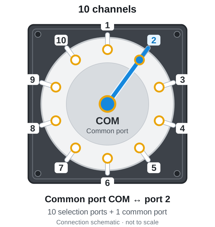
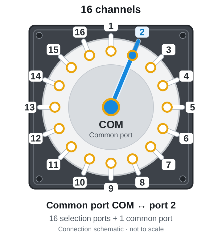
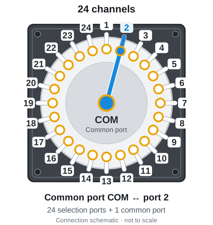
These original connection schematics explain channel counts and connectivity. They do not specify a product's appearance, port locations, internal dimensions or actual numbering direction. Use the product's fluidic diagram and control protocol to confirm common-port counting, rotation direction and channel numbering.
Equal channel or position counts do not establish equal connections, wetted materials or pressure ratings. Channel count determines whether enough connections are available; other parameters must still be checked individually.
For example, a two-position, six-port switching valve alternates between two connection states, while a multiposition selector connects COM to one path at a time. Both use rotation but perform different tasks. Specifying only a six-port or multichannel valve is often insufficient for procurement.
Also check the destination of unselected streams. Depending on the design, they may be dead-ended, routed to another common outlet or kept flowing through individual outlets. The diagrams above show only the dead-ended arrangement, not every multiposition rotary configuration.
Likewise, 24 selectable channels do not mean 24 paths can meter liquid independently at the same time. Simultaneous sample processing also requires consideration of separate pumps, metering units and the complete fluidic architecture.
04What tasks do rotary valves perform in instruments?
Reagent selection: one mechanism accesses different liquids sequentially
When several reagents must be dispensed in sequence, their sources can connect to selection ports. The program selects a source before the pump delivers it. One downstream path can serve multiple sources, but sharing it also requires attention to residual liquid and cleaning.
Sample preparation and washing: connecting successive process steps
Sampling, adding processing solutions and washing may require different liquids. The valve switches connections by process step, while the pump and positioning mechanism deliver liquid to the target vessel or waste position. If samples pass through the valve, assess particles, adhesion and carryover in addition to mechanical movement.
Chromatographic injection: changing the connections of an entire circuit
A suitable injection switching valve with an external sample loop changes connections between loading and injection states. This task has specific flow-path and pressure requirements. An ordinary reagent selector must not be assumed to serve as a high-pressure injection valve.
05A complete example: switching from reagent A to reagent B
Assume A, B and a wash solution occupy separate selection ports, while COM connects to one pump and dispensing needle. To prevent wash liquid from entering the reaction vessel, move the needle to waste or provide another verified waste-routing arrangement. This example uses a movable dispensing needle.
- Finish dispensing A, bring the pump and fluid path into conditions that permit switching, and move the needle to waste.
- Select the wash solution, confirm the valve position and use the pump to flush the connected shared path into waste.
- Switch to B and use it to displace wash liquid from the shared path. Discard this displacement volume at waste.
- Once replacement meets the process requirements, return the needle to the target vessel and meter B.
- Finish AEstablish switching conditions
- WashFlush into waste
- Displace with BRemove the previous liquid
- Meter liquidDispense into the target vessel
Cleaning performance depends on the entire connected path: valve passages, tubing, fittings, pump chamber and dispensing needle. Small valve internal volume reduces liquid retained inside the valve, but does not establish a carryover-free system.
06From operating principle to practical selection
List the liquid sources and destinations, then draw the connections needed at every step. Once these are clear, compare channels, bore size, fittings, pressure conditions and wetted materials. MRV3 configurations with 10, 16 or 24 channels are candidates for sequential selection among multiple sources; suitability depends on the actual conditions.
07Rotary valve FAQs
Can a rotary valve directly control the volume dispensed each time?
A rotary valve primarily changes connections. Dispensed volume is usually determined by pump metering, liquid conditions and the installed fluid path. Valve internal volume or switching count cannot substitute for dispense volume.
How does a rotary valve differ from a solenoid valve?
A typical electric rotary valve changes connections by rotating a rotor; a solenoid valve uses electromagnetic force to open, close or switch paths. Function also depends on the flow-path arrangement. Selection, independent shutoff and simultaneous operation are different requirements; actuation method alone does not determine superiority.
Can the last channel number be reused after power loss?
Establish the actual position using the model's homing and position-confirmation procedure. A saved software channel number does not prove that the physical position is unchanged. Confirm position before operating the pump.