
Microfluidic Hard-Tube Fitting Selection Guide: Flanged, Ferrule and Snap-Ring Connections
Selection essentials: Check port geometry, tubing OD and fluid first, then pressure, maintenance frequency and tube-end preparation. Flanged fittings press a tube-end flange against a flat sealing face; ferrules grip the tube as the fitting tightens; snap-ring designs use a sleeve and sealing ring. Matching threads and tube diameters alone do not establish compatibility.
For equipment developers, fluid-system designers and maintenance engineers, this guide builds a shortlist from sealing geometry, interfaces, fluids, pressure and disconnection requirements. A fluid-path example then combines tubing, light shielding and mechanical protection.
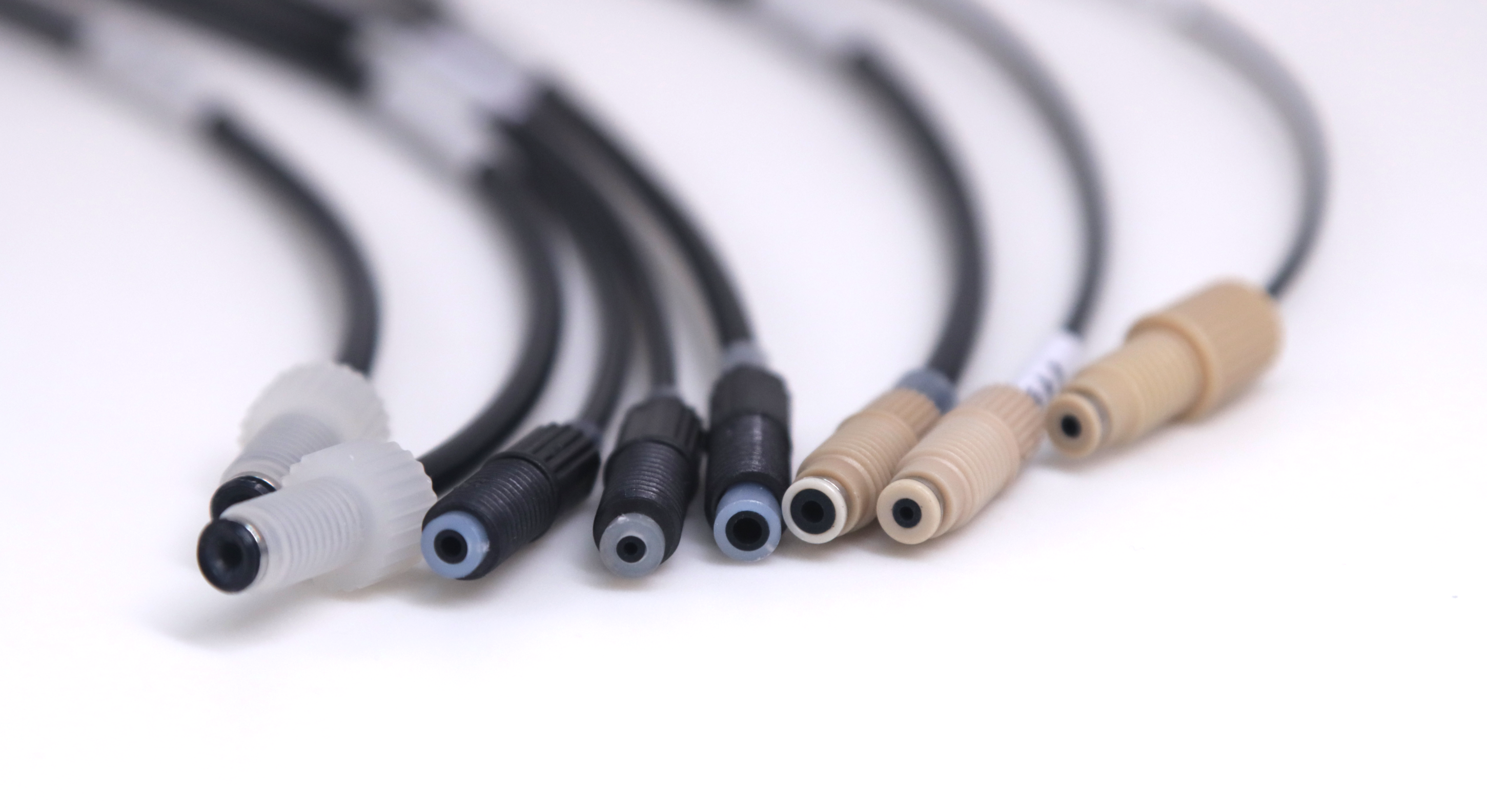
01How do the three connection types seal?
Flanged, ferrule and snap-ring fittings secure and seal the tube end differently. Establish tube-end preparation and sealing-face location before matching the fitting and its components.
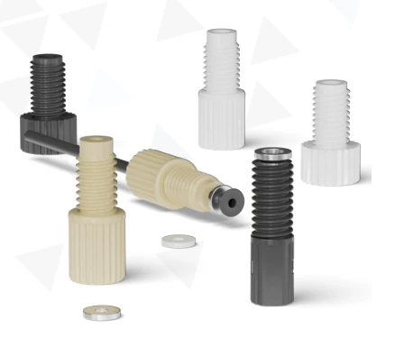
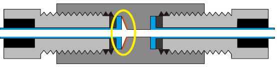
Flanged: a tube-end flange contacts the flat sealing face
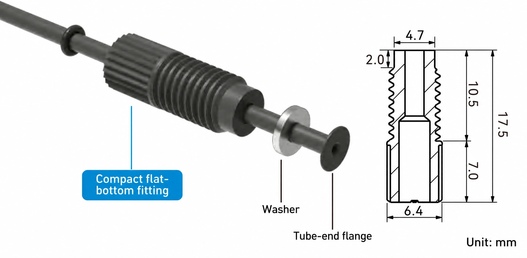
Flangeable tubing such as FEP or PTFE is first formed at the end, then assembled with the matching washer and fitting. In this structure, the washer sits between the flange and fitting body, supporting the flange and transferring compression. Tightening seats the flange against the flat port bottom to form the seal.
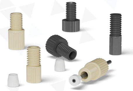
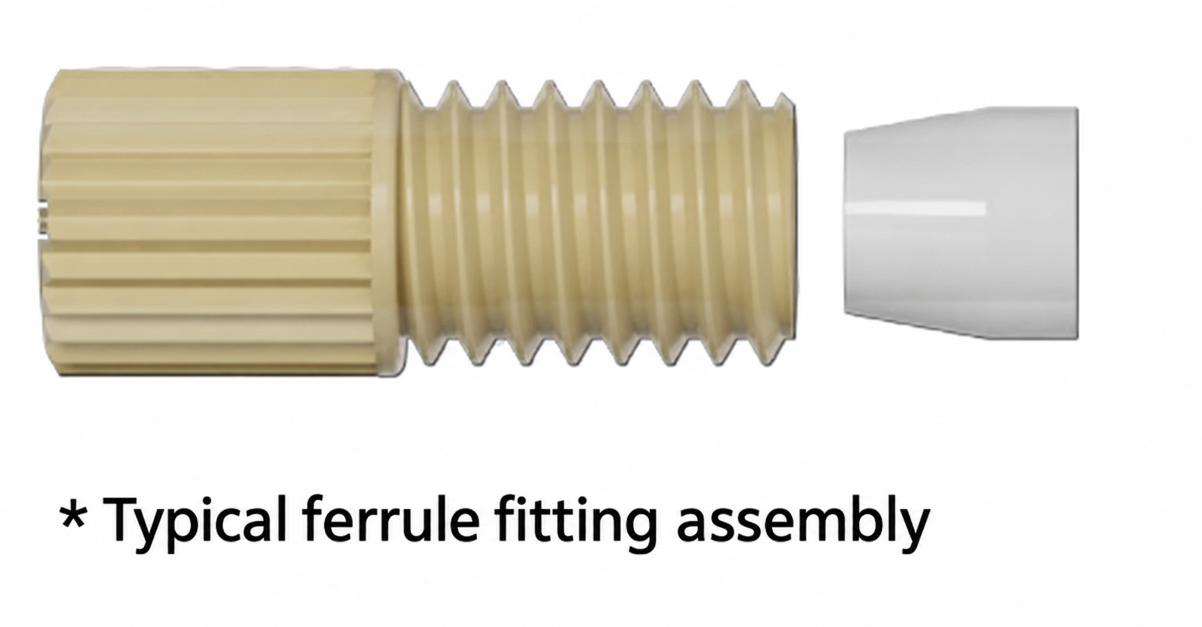
Ferrule: tightening grips the tube and seals at the port bottom
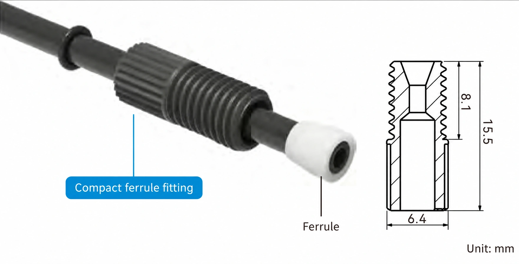
No tube-end flanging is needed. Slide the fitting and matching ferrule onto square-cut tubing and position them as specified. Tightening compresses the ferrule around the tube wall and against the port sealing face. Confirm ferrule size, orientation and compatible fitting series before assembly.
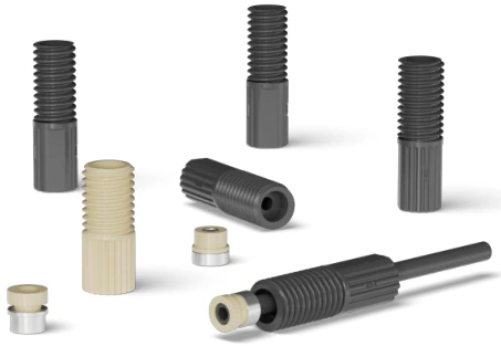
Snap-ring: a sleeve and sealing ring form the tube-end assembly
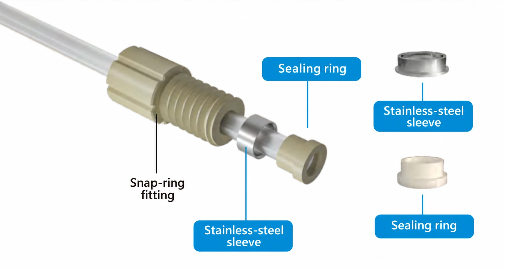
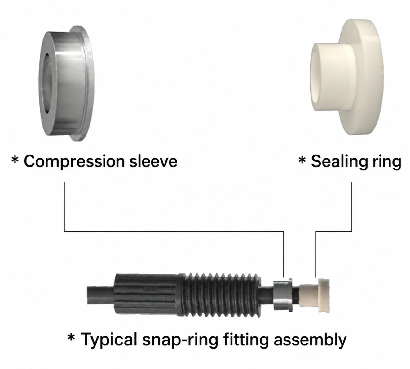
Slide on the fitting, sleeve and sealing ring in sequence. Align the tube end flush with the ring face, then compress according to the assembly instructions. The CL-1S kit combines a PEEK sealing ring with a stainless-steel sleeve and the corresponding HSF6 fitting for face sealing. During connection, the fitting can rotate relative to the tube, reducing tube twisting while tightening.
Follow the assembly instructions for the specific snap-ring model. Preassembly steps and special tools depend on the selected kit.
Selection note: Ferrule and snap-ring fittings both avoid tube-end flanging, but use different parts and assembly methods. Check the matching fitting, ferrule or snap-ring components; equal threads and tube diameters do not make them direct substitutes.
02What are the advantages and reuse limits of each design?
With a stable flanging process, assess flanged fittings first; for assembly without flanging, assess ferrule fittings; for preassembled tubing and maintenance disconnection, assess snap-ring fittings. Separately confirm whether a complete assembly may be reconnected and whether removed sealing parts may be reinstalled.
Flanged: suitable for preassembled tubing; flange quality is fundamental
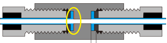
A formed flange defines the connection position and supports repeatable prefabrication and assembly. Limitations include the forming process, end-face flatness and port-bottom geometry. A damaged flange, excessive compression or an incompatible conical port can prevent reliable sealing-face contact. Inspect the flange and washer before reconnecting.
Ferrule: convenient first assembly, subject to single-installation limits
Square-cut tubing can be assembled without flanging. The ferrules covered here are for a single installation; reinstalling them may cause irreversible plastic deformation. Prepare matching new ferrules for maintenance.
Before reconnecting the original tube with its original ferrule, obtain written reuse instructions for that exact combination. Assess reuse of the fitting nut separately, based on its condition and assembly requirements.
Snap-ring: repeated reconnection still requires tube-end inspection
A complete tube-end assembly using HSF6 and a matching snap-ring kit can be disconnected and reconnected as specified, making it a candidate for serviceable prefabricated fluid paths. Inspect it before each reconnection. Confirm allowable cycles and life for the exact combination and operating conditions. Removing an old sleeve and pressing it onto a new tube requires separate confirmation that the kit permits reinstallation.
| Selection factor | Flanged | Ferrule | Snap-ring |
|---|---|---|---|
| Initial tube-end preparation | Form a flange and use a matching washer | Square-cut end with a matching ferrule | Square-cut end; locate sleeve and sealing ring |
| Disconnection and reconnection | Reconnect as specified with flange and washer intact | Replace ferrules according to single-installation limits | Reconnect the complete assembly as specified |
| Key checks | Flange flatness and port-bottom geometry | Ferrule size, orientation and deformation | Pressing position, orientation and flush tube end |
| Needs to assess first | Established flanging process or outsourced preassembly | No flanging; ferrule replacement during maintenance | Preassembled tubing and maintenance disconnection |
Matching parts: HN / HN6 use CL-0X; HNF / HNF6 use CL-0. Check the fitting series and ferrule model separately when ordering.
03How do pressure, vibration and maintenance narrow the shortlist?
| Known condition | Next selection step |
|---|---|
| Port and tubing OD are defined | Check threads, flat or conical bottom, sealing location and insertion depth; exclude geometrically incompatible combinations. |
| No flanging tools or stable process | Assess connections without flanging or supplier-preassembled flanged tubing. |
| Repeated maintenance disconnection | Assess flanged or snap-ring assemblies approved for reconnection and check reuse conditions; include replacement ferrules in ferrule-system maintenance costs. |
| Sustained pressure, temperature or pulsation requirements | Request data for the exact fitting, tubing and port combination. Keep combinations with insufficient data as candidates requiring validation. |
| Tubing moves with the mechanism | Assess routing, motion allowance, bend radius and strain relief so motion loads do not concentrate at the fitting root. |
For a rarely disconnected suction line, start with airtightness, resistance to tube collapse and interface fit. For regularly serviced connections, compare reconnection conditions for the complete tube-end assembly and seal replacement costs. Near moving mechanisms, address motion allowance, guidance and strain relief separately.
Validate real failure risks after shortlisting
| Operating condition | Main risk | Validation task |
|---|---|---|
| Long-term sustained pressure | Material creep and changes in gripping force | Hold pressure for the project-defined duration using the intended fluid and maximum operating temperature; check leakage, movement and pullout. |
| Start/stop operation and pressure pulsation | Loosening or fatigue from repeated loading | Record pressure peaks and cycling conditions; inspect seals before and after cycling. |
| Suction under negative pressure | Small air leaks, bubbles and tube-wall deformation | Check connection airtightness and tube-collapse resistance; investigate the source of any bubbles. |
| Vibration and equipment movement | Pulling and wear concentrated at the tube end | Validate supports and strain relief; check loosening and leakage after vibration. |
| Regular disconnection | Damage to flange, sealing ring or ferrule | Define disconnection procedures, inspection methods and replacement criteria, then validate the serviced connection. |
Use these tasks in the installed-system validation plan. Specify test temperature, sustained and peak pressures, vacuum conditions, cycle counts and permissible leakage. Judge each model against its specifications and test results.
High-pressure fluid paths require separate selection. The manual's maximum pressure of 34 MPa applies to dedicated high-pressure fittings, not the ordinary flanged, ferrule or snap-ring designs discussed here. Use the specific model's rated data for the actual temperature, tubing and installation conditions.
04How should FEP and PTFE tubing be selected, and when is light shielding needed?
Tubing OD determines fitting compatibility; ID and length affect flow resistance and internal volume; material determines basic fluid and mechanical suitability. Establish working and cleaning fluid composition, concentration, maximum temperature and contact time before selecting tubing and wetted sealing materials.
| Tubing | Main characteristics | Observation and light shielding | Selection priorities |
|---|---|---|---|
| FEP | Natural-color tubing is relatively transparent for fluid-path observation | Helps observe fluid and bubbles; assess extra shielding for light-sensitive fluids | Check fluid, wall, pressure and bending conditions. Resistance to UV aging does not mean UV light is blocked. |
| PTFE | High chemical inertness, low friction coefficient and flangeable ends | Natural, black and specific transparent grades are available | Confirm color and transparency by model; validate black tubing's shielding for wavelength and wall thickness. |
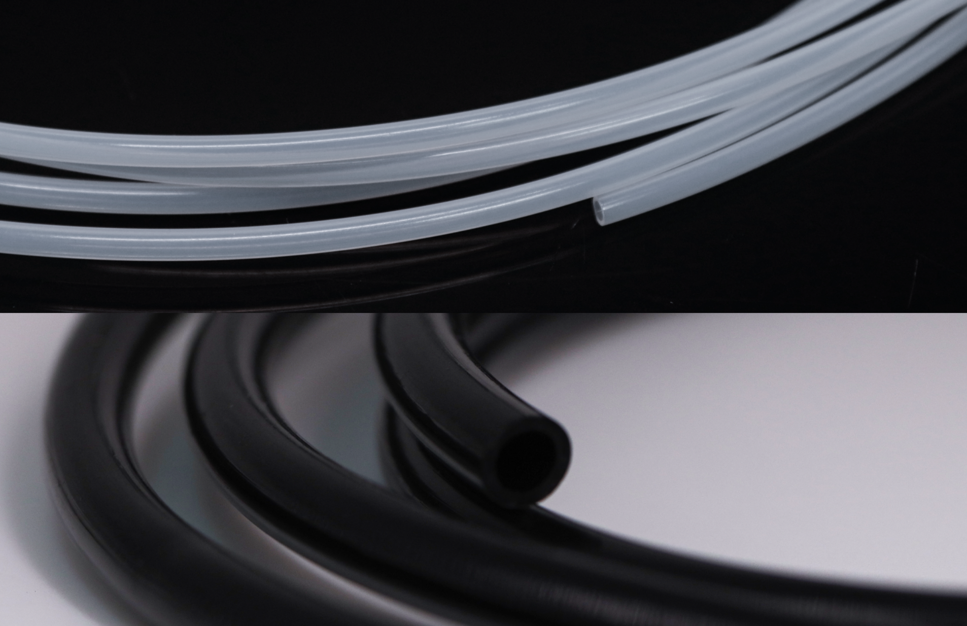
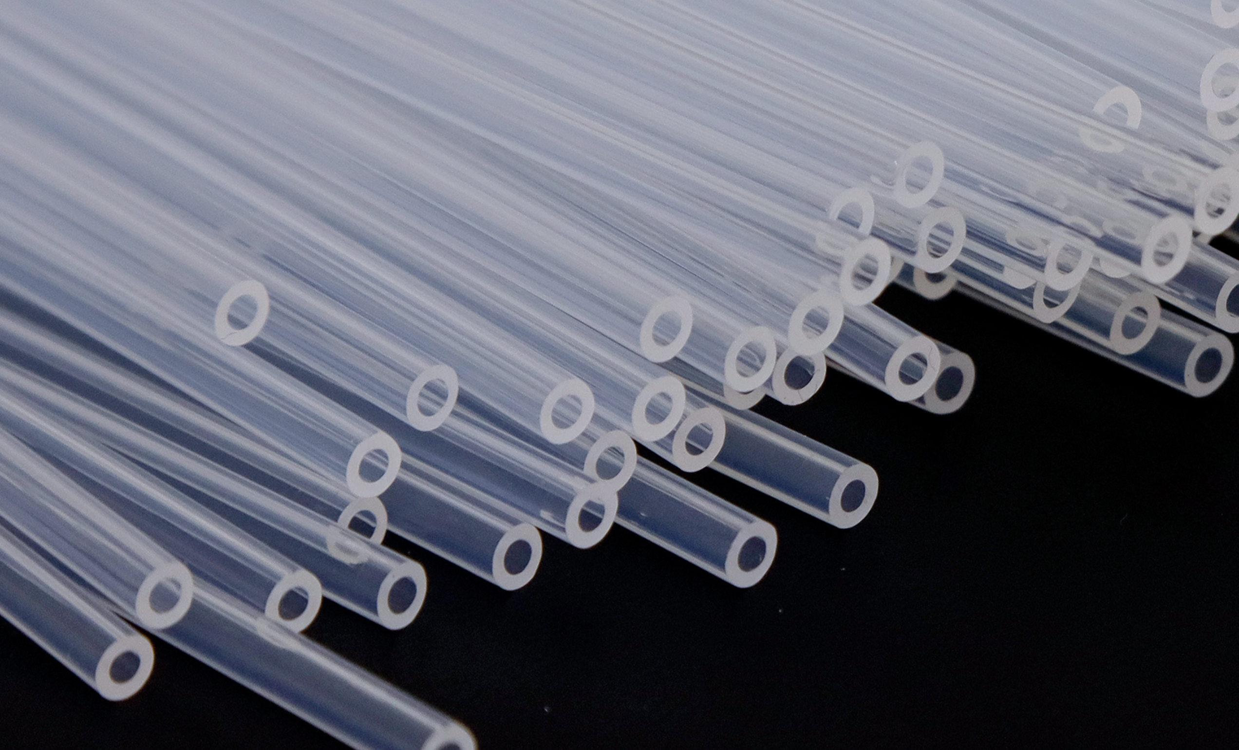
FEP and PTFE tubing have some flexibility; observe the minimum bend radius for each specification. In continuously moving sections, assess kinking, wear and fatigue. Static bend capability does not establish suitability for repeated flexing.
Which tubing specifications are candidates for 2.5 mm OD?
| Tubing model | Material / color | OD / ID | Selection considerations |
|---|---|---|---|
| BFT03008 | FEP / natural | 2.5 / 1.5 mm | Size candidate for bubble observation; design light shielding separately. |
| TH2-PTFE-B-15-25 | PTFE / black | 2.5 / 1.5 mm | Candidate for black tubing; measure shielding at the sensitive wavelengths. |
Both listed models are candidates with 2.5 mm OD and 1.5 mm ID; selection also depends on fluid, pressure and shielding needs. Transparent PTFE model TH2-PTFE-T-20-32 is another option whose dimensions and conditions must be checked separately.
What if both light shielding and bubble observation are required?
Assess transparent tubing with a full light-blocking sleeve, or a short observation section in a controlled position covered during normal operation. Include exposed areas near fittings, cover opening during maintenance and actual lighting in the assessment. Decide based on fluid-sensitive wavelengths, transmission, exposure time and fluid stability results.
05How should tubing be protected against wear, bending and motion?
| Risk location | Suggested measure | Validation focus |
|---|---|---|
| Tubing touches metal edges or brackets | Reroute and add smooth guides or abrasion-resistant sleeves | Edge contact, sleeve migration and crushing at support points. |
| Sharp bend at the fitting root | Use a gradual-bend guide; assess a limiting sleeve or anti-kink spring for the structure | Minimum bend radius, local kinking and new stress concentration at the protector end. |
| Cyclic displacement of moving parts | Allow travel, guidance and strain relief; assess coiled recoil tubing where suitable | Stroke, pulling force, maximum extension and motion-cycle life. |
| Vibration puts tension on fittings | Position retaining clips appropriately and avoid overly close rigid constraints | Support-point wear, tube-end movement, leakage and loosening after vibration. |
| Fluid requires light shielding | Choose shielding tubing or a sleeve and cover exposed areas near connections | Transmission at sensitive wavelengths and shielding integrity after maintenance. |
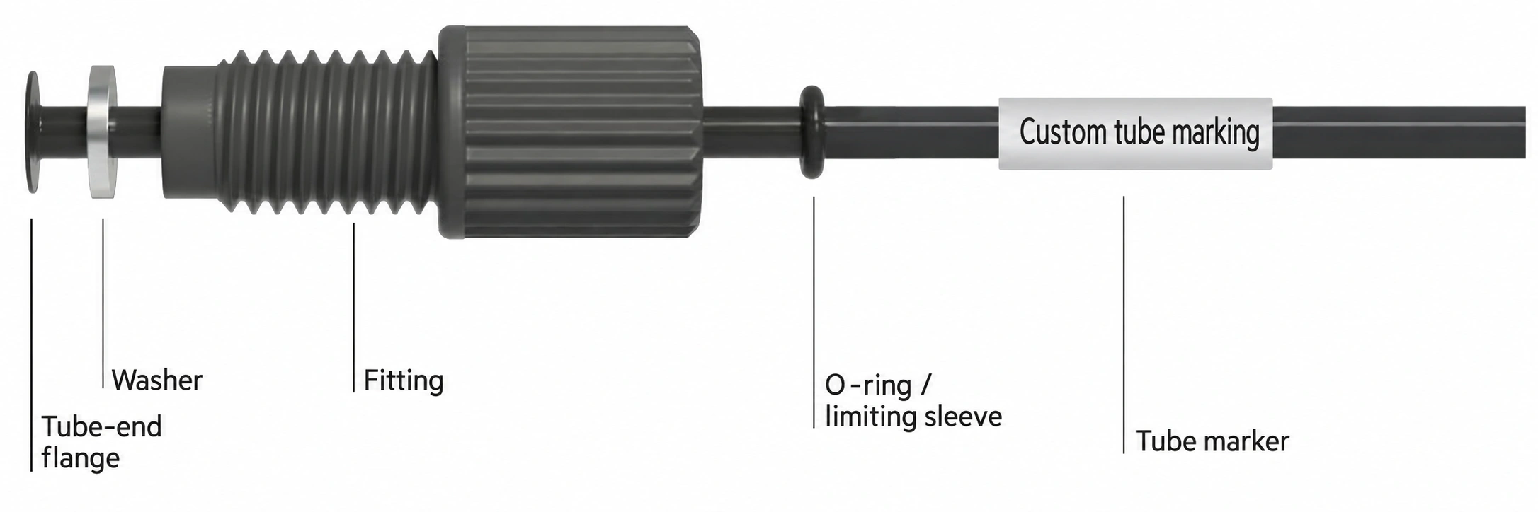
FOREACH preassembled tubing can use the illustrated O-ring, limiting sleeve and tubing identification configuration as a reference. Design abrasion sleeves, anti-kink springs or coiled recoil tubing for the available space, travel and loads, and separately confirm form and supply scope.
Abrasion sleeves, anti-kink features and motion allowance reduce rubbing, sharp bending and pulling risks respectively; they do not increase allowable internal working pressure.
06How are fittings and tubing assemblies selected for a complete fluid path?
Example conditions: 2.5 mm tubing OD, M6×1 port thread, maintenance disconnection and a section near a moving mechanism. Light-sensitive fluids also require shielding. The following selection shortlists connection parts and tubing, then identifies operating conditions to confirm before finalizing.
Check the port, operating conditions and maintenance method first
- Confirm the port. M6×1 specifies only the thread; also check the flat sealing face, hole depth, tube-end position and assembly space.
- Confirm fluids and fluid path. Provide working and cleaning fluid composition, temperature, target flow, tube length and allowable pressure drop to assess whether 1.5 mm ID is suitable.
- Confirm maintenance. To retain a complete tube-end assembly during service, compare flanged and snap-ring designs; for ferrule connections, include new ferrule installation in the service procedure.
| Candidate approach | Model and matching dimensions | Conditions and checks still required |
|---|---|---|
| Option 1: preassembled flanged tubing | HFL-M6-25-PV-B: M6×1, 2.5 mm OD, PVDF, black. For the WS washer size series for M6 / 2.5 mm tubing, refer to WS-46-26. | A qualified flanging process is required. Select washer material for the assembly and verify the port and complete assembly's allowable pressure. |
| Option 2: preassembled snap-ring tubing | HSF6-M6-32-PS-B + CL-1S-25: M6×1 fitting with a 2.5 mm snap-ring kit; PEEK sealing ring plus stainless-steel sleeve. | This HSF6 fitting specification accepts 2.0 / 2.5 / 3.0 / 3.2 mm tubing; the example uses the 2.5 mm kit. Position and compress as instructed. |
Then select tubing, shielding and moving-section protection
For bubble observation, assess natural FEP BFT03008 with shielding as the fluid requires. For black tubing, assess TH2-PTFE-B-15-25 and validate actual light blocking. Both candidates have 2.5 mm OD and 1.5 mm ID; confirm fluid compatibility and working pressure separately. Near moving mechanisms, add supports, motion allowance and guides.
Complete the shortlist and final validation
Record fitting models, matching parts, tubing and protection. Define sustained and peak pressures, vacuum conditions, temperature, fluid compatibility, allowable pressure drop and disconnection frequency before drawing review and sample evaluation. Confirm working pressure and life for the entire combination under actual conditions.
Before final selection, include sealing, vacuum airtightness, reconnection, motion wear and light shielding in the acceptance plan. Record conditions and results, then finalize the bill of materials, assembly process and maintenance replacement rules.
View hard-tube fitting series and specificationsView HFL-M6-25-PV-B
07Frequently asked questions
Can a leak be fixed by tightening further or adding thread adhesive?
Stop, depressurize and locate the leak, then inspect the port, tube end and matching seals. These three connections seal through the tube end or mating components; threads mainly provide compression. Extra force may damage flanges, ferrules or rings. Replace damaged threads, sealing faces or tube ends as the model requires and retest. Do not add adhesive, thread tape or lock washers unless assembly instructions permit them; they can change installation depth, compatibility or cleanliness.
Why does a connection pass a static check but leak when the pump or tubing moves?
A static check covers only the pressure, temperature and loading at that time. Record start/stop events and pressure pulsation, and check for tension, twisting or sharp bends at the fitting root. Review routing, supports and travel allowance, then reproduce the issue with the actual fluid, temperature and motion. Compare leakage, tube-end displacement and flow before and after adjustment. One static pressure-hold pass does not validate the installed system.
Must I switch to a flanged fitting if flow falls after installing a ferrule fitting?
Reduced flow alone does not prove that a ferrule design is unsuitable. Check tube ID and fitting passage, cut-end burrs, insertion position, sharp bends and excessive tube-end compression. Compare flow and pressure drop with the same fluid, temperature, tube length and pump conditions before changing assembly, size or connection design. Equal tubing OD does not imply equal internal passages or flow resistance.
Why does a water-tested connection leak with the working or cleaning fluid?
Water testing does not replace actual-fluid compatibility validation. List working fluids, cleaners and possible residual mixtures. Check tubing, fittings and seals against composition, concentration, temperature and contact time. Investigate swelling, hardening, cracking or dimensional change, replace incompatible parts, then validate assembly sealing and flow again. Broad claims such as acid/alkali or solvent resistance are insufficient.
Can the original ferrule, snap-ring kit and fitting be reused after maintenance?
Distinguish reconnecting a complete tube-end assembly from pressing removed parts onto tubing again. Prepare new ferrules according to the single-installation requirement; retaining the original tube and ferrule for reconnection requires written instructions for that exact combination. A reconnectable snap-ring assembly does not imply its sleeve and ring may be moved to new tubing. Inspect fitting threads, appearance and assembly condition separately, then retest after maintenance.
Does black tubing solve both light exposure and tubing aging?
Color alone is insufficient. Validate shielding against fluid-sensitive wavelengths, wall thickness and transmission. Investigate cracking or life issues separately for fluid, temperature, pressure pulsation and repeated flexing. Black tubing or a shielding sleeve cannot replace compatibility and motion-life validation. If bubbles must remain observable, assess a controlled short viewing section or removable shielding, and verify shielding integrity during operation and after service.