
How to Select Flanged Tubing Assemblies: Sealing, Port Matching and Installed Validation
In analytical instruments and automated fluid paths, tubing assemblies connecting pumps, valves and fluidic modules must meet sealing, routing and replacement needs as well as transport fluid. Making a connection is only part of the task: the tube flange, backing washer and receiving port determine whether compression acts at the intended sealing surface.
For existing flanged interfaces, check the original assembly and port drawings first. For a new OEM fluid path, define the configuration around routing, port spacing and maintenance. The following sections cover assembly structure, materials and dimensions, fitting selection and installation checks.
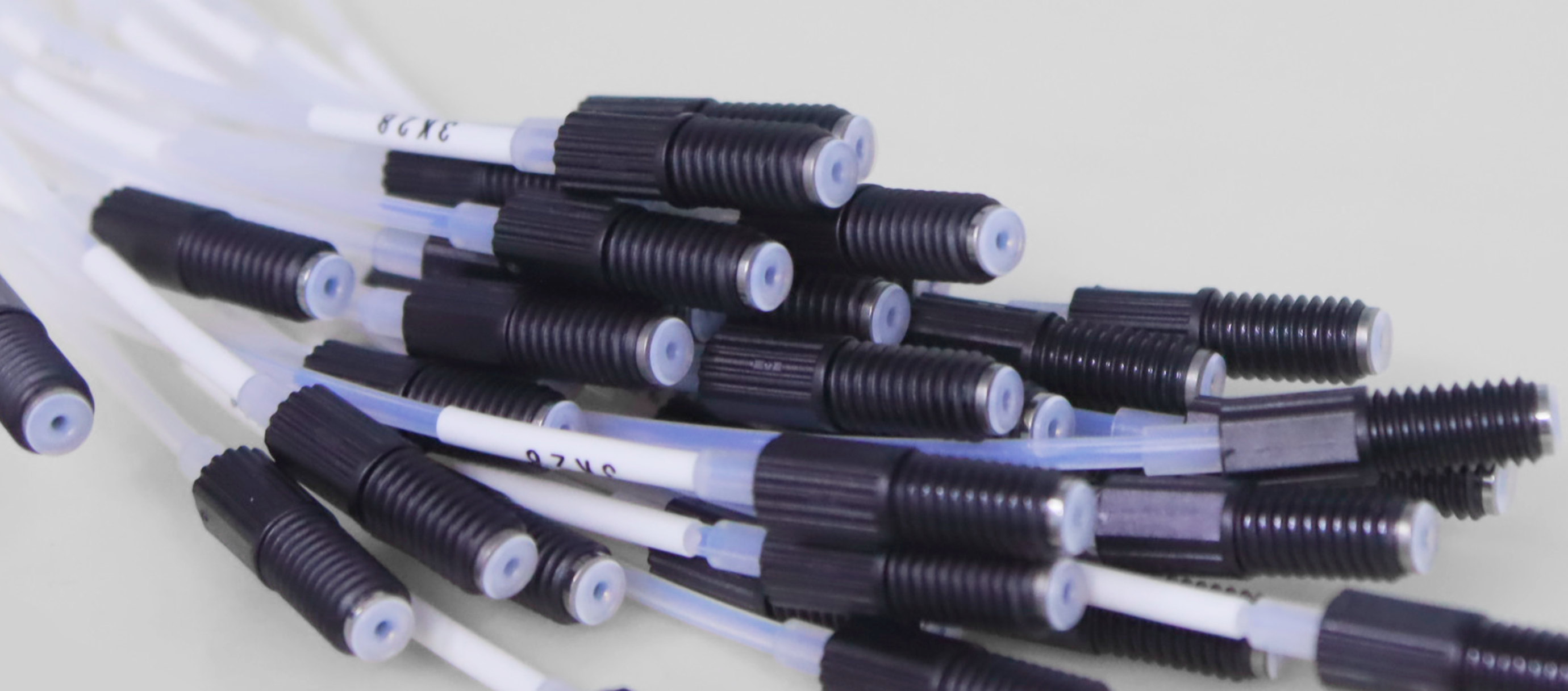
01What makes up a flanged tubing assembly, and how does it seal?
The preformed tube end has an outward-facing flange. During assembly, the threaded fitting applies axial force through a matched backing washer, supporting and compressing the flange against the sealing face of a compatible flat-bottom port. Check thread engagement and face sealing separately: a fitting that screws into a port does not necessarily seat the flange against its bottom.
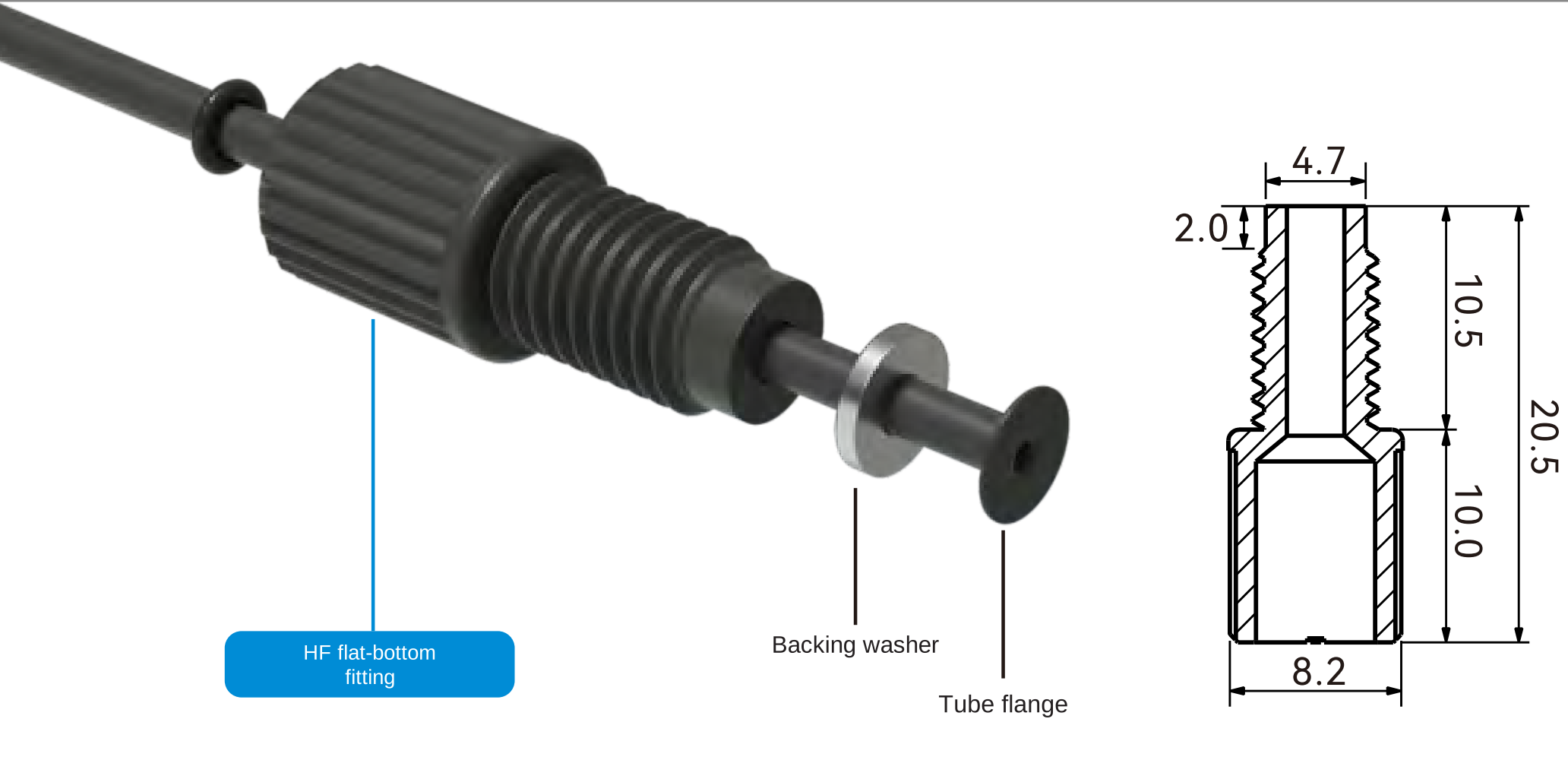
HF, HF6, HFL and HFL6 flat-bottom fittings are available for flanged tubing assemblies. HF and HFL have standard heads; HF6 and HFL6 are compact types. All use matched washers to compress the tube flange, but head dimensions, overall length, bores and nose geometry differ. Select a specific series and model; one set of dimensions cannot represent every fitting.
| Component | Main function | What to confirm |
|---|---|---|
| Tubing and formed flange | Transport fluid; the formed tube end provides the face seal | Material, ID/OD, length, single- or double-ended flanging and formed dimensions |
| Threaded fitting | Engage the port and apply axial compression | Series, material, thread, through-bore and installation space |
| Backing washer | Support the flange and transmit compression | Material, ID, OD, thickness and compatibility with the fitting |
| O-ring / retaining sleeve | Limit fitting movement along the tubing | Whether required, position and permitted travel |
| Tubing label | Identify the fluid path, port or installation position | Content, orientation, position and correspondence between ends |
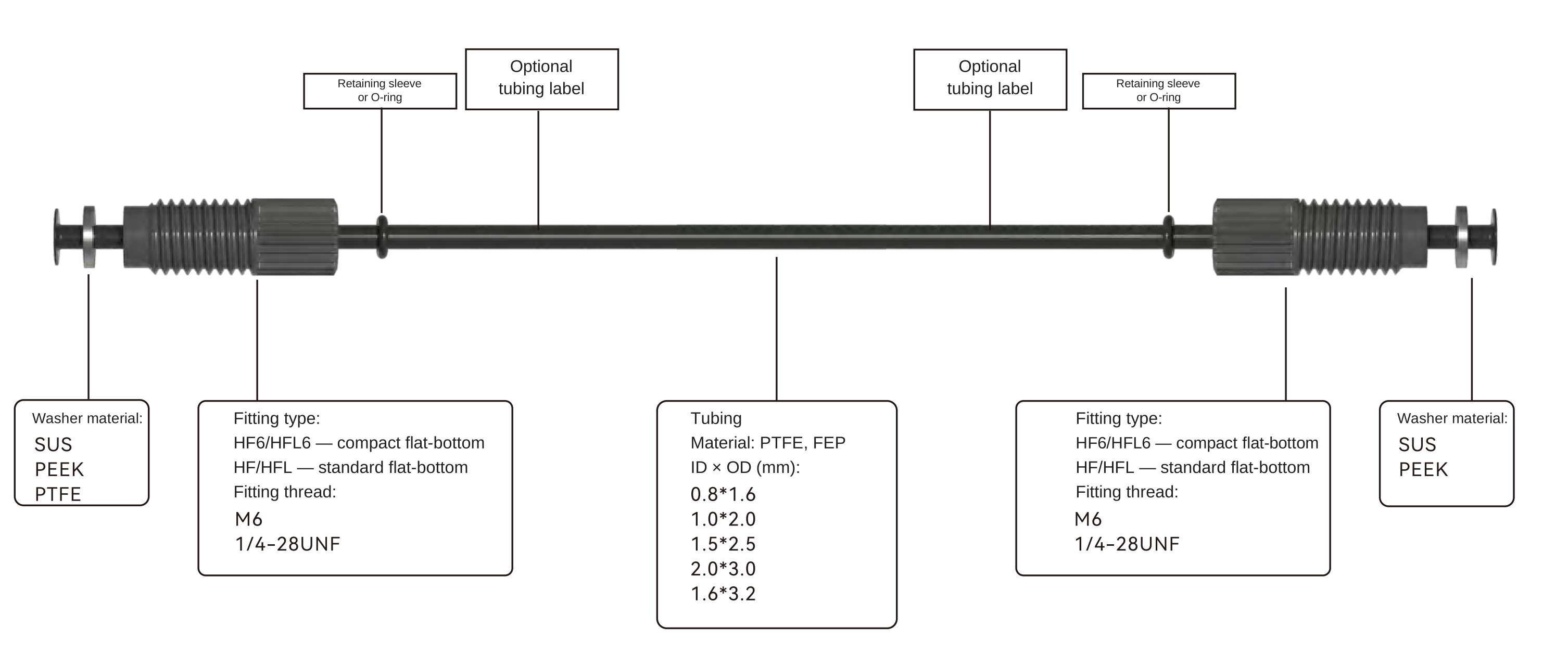
The O-ring or retaining sleeve behind the fitting limits sliding; it is not the receiving port’s seal. If the end interfaces differ, confirm the fittings and washers independently rather than assuming an identical configuration at both ends.
02How should tubing material, fitting material and tubing size be specified?
| Part | Listed configurations | Selection boundaries |
|---|---|---|
| Tubing | FEP, PTFE | Confirm chemical compatibility and suitability for the flanging process separately |
| HF / HF6 fitting body | PEEK, PVDF, PPS | Check the material, thread and tubing OD combination for the specific model |
| HFL fitting body | PVDF | Select the specific thread, tubing OD and color configuration |
| HFL6 fitting body | Listed M6×1 and 1/4-28 UNF versions use PPS; the listed small 6-40 UNF version uses PEEK | Do not transfer material specifications between different threads and sizes |
| Matched backing washer | SUS stainless steel, PEEK or PTFE, depending on size | Check ID, OD and thickness; not every size is available in every material |
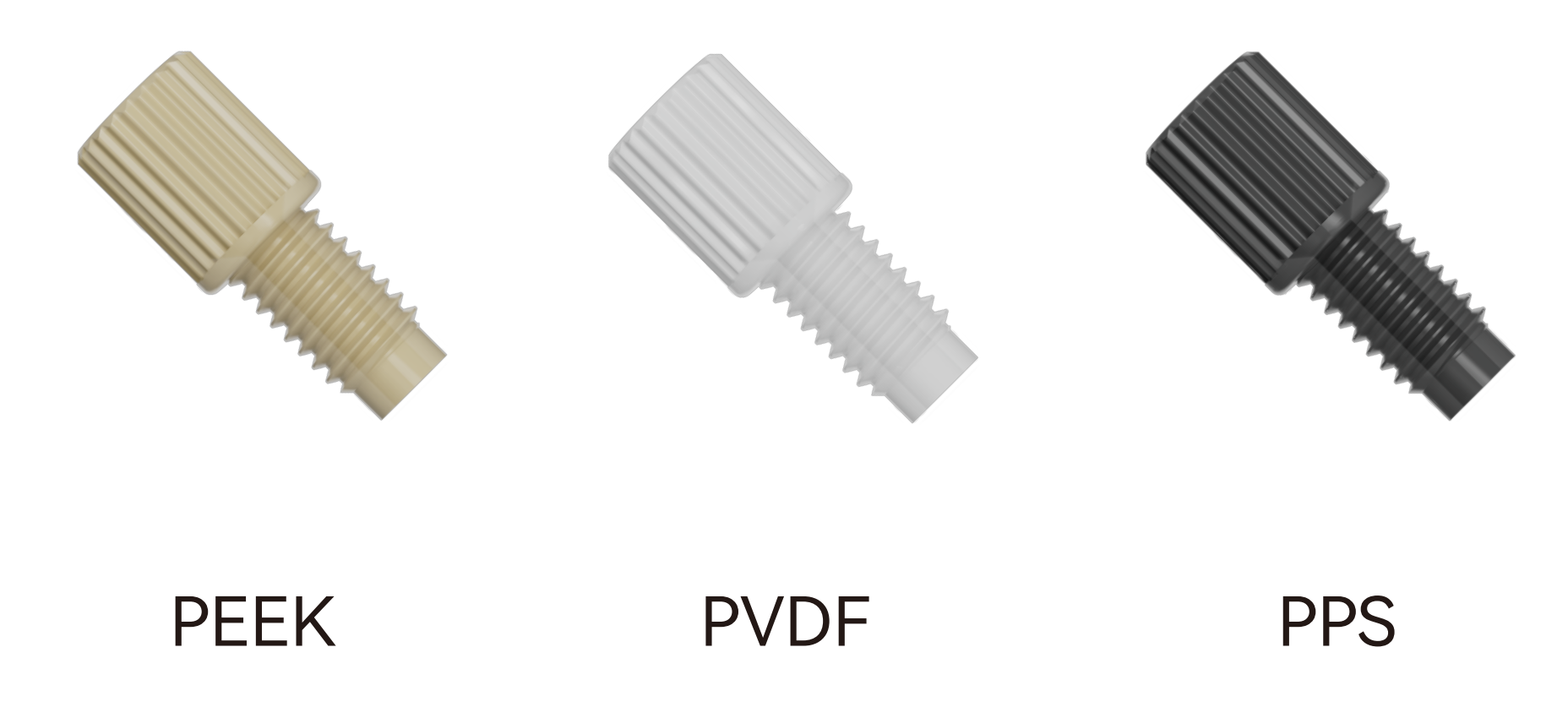
Specify tubing ID, tubing OD and fitting through-bore separately. ID and length affect flow resistance and internal volume; OD determines the fit with the fitting, washer and forming tool. The fitting bore must provide suitable clearance for the selected tubing OD. Calling all three “tube diameter” is ambiguous.
The current assembly documentation lists tubing ODs of 1.6, 2.0, 2.5, 3.0 and 3.2 mm. Specify ID and OD as a pair. For example, 0.8 × 1.6 mm in the configuration diagram means ID × OD, not two compatible tubing ODs. Match the pair to the selected material and forming requirements.
Chemical resistance alone does not make every wall thickness suitable for the same flanging process. Confirm the tooling, material and ID/OD range before forming; inspect end integrity and the flow passage afterward. Define the length datum in the drawing, such as the distance between sealing faces, to avoid confusing cut length with finished assembly length.
03How do HF, HF6, HFL and HFL6 flat-bottom fittings compare?
All four series offer M6×1 and 1/4-28 UNF configurations. Check thread, tubing OD and material first, then compare head diameter, axial length and nose geometry. Dimensions below follow the series drawings linked on the website, in mm. They exclude the tube flange and washer and are not the exposed length after installation.





| Series | Head OD / overall length | Tubing OD | Body material |
|---|---|---|---|
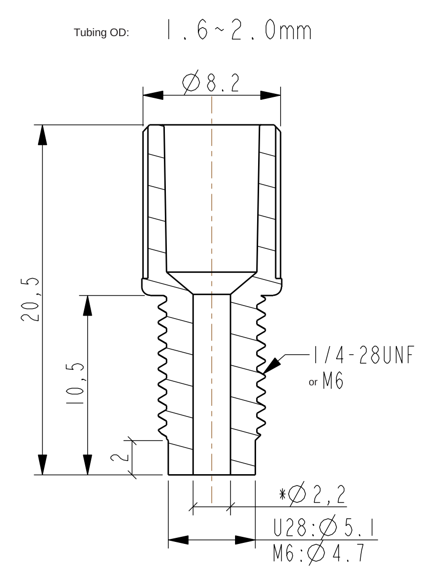
| HF standard flat-bottom | 8.2 / 20.5 | 1.6–2.0, 2.5, 3.0–3.2; three size groups | PEEK, PVDF, PPS |
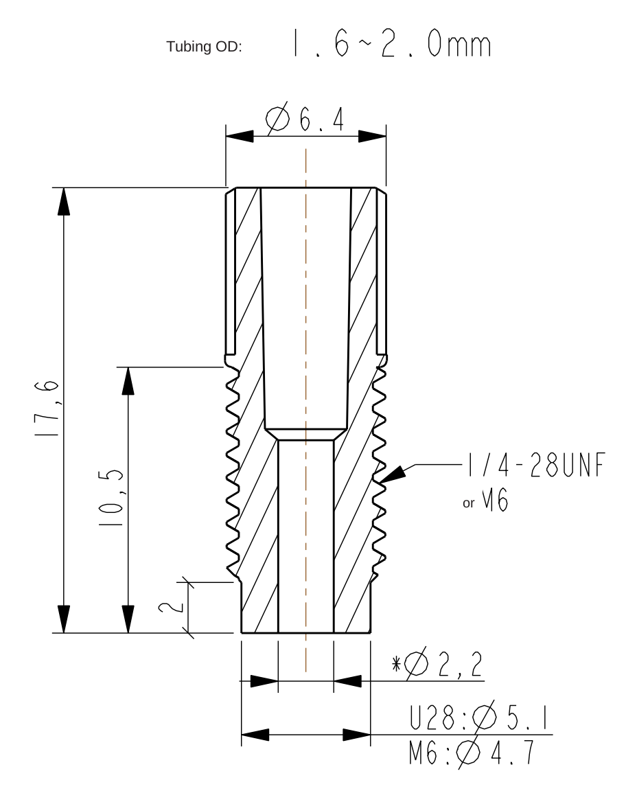
| HF6 compact flat-bottom | 6.4 / 17.6 | 1.6–2.0, 2.5, 3.0–3.2; three size groups | PEEK, PVDF, PPS |
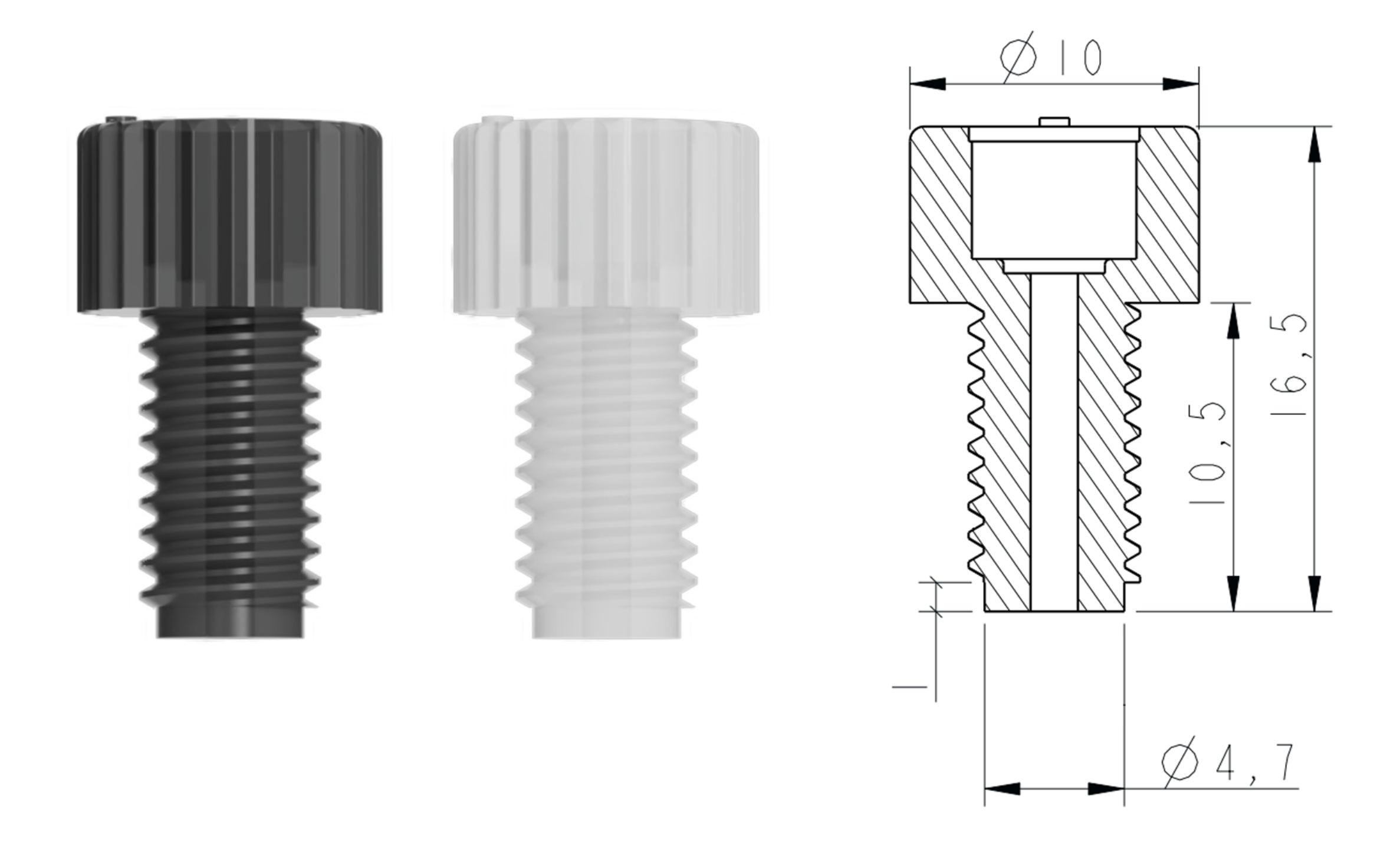
| HFL standard flat-bottom | 10 / 16.5 | 1.6, 2.0, 2.5, 3.0, 3.2; select each OD separately | PVDF |
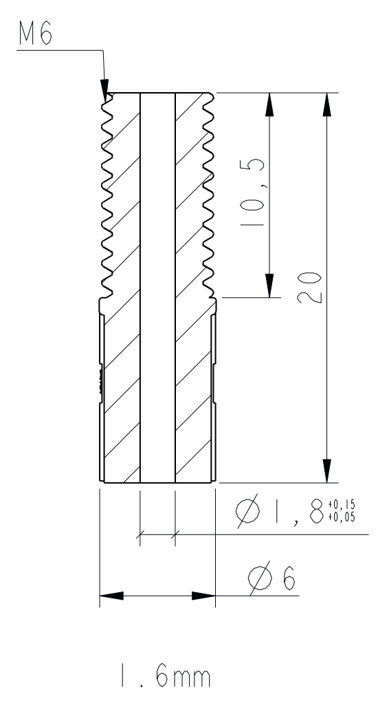
| HFL6 compact flat-bottom | 6 / 20 | 1.6, 2.0, 2.5, 3.0, 3.2; select each OD separately | PPS; this row covers M6 and U28 versions |
HF: standard head, three tubing OD groups
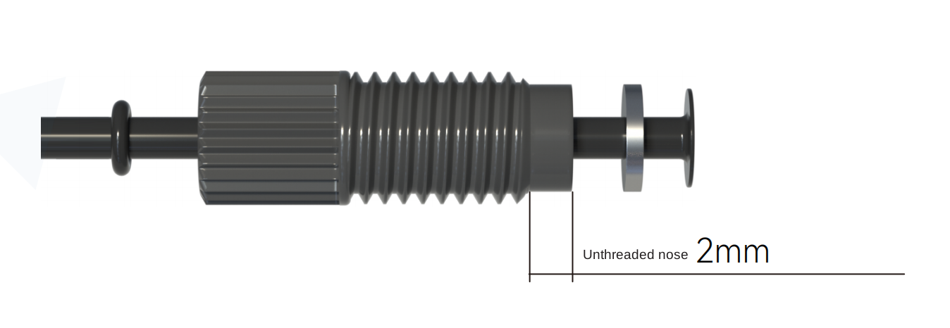
HF has an 8.2 mm head diameter, 20.5 mm overall length and a 2 mm unthreaded nose. The three tubing OD groups—1.6–2.0, 2.5 and 3.0–3.2 mm—have drawing bore sizes of 2.2, 2.7 and 3.4 mm respectively. Select PEEK, PVDF or PPS by model, and check turning clearance around the head and tubing exit space behind it.
Drawing: HF flat-bottom fitting dimensions (M6 / 1/4-28 UNF)
HF6: a narrower and shorter compact alternative to HF
HF6 has a 6.4 mm head diameter and 17.6 mm overall length, respectively 1.8 mm and 2.9 mm smaller than HF. Its tubing groups, body materials and 2 mm nose clearance match the corresponding HF configurations. Consider HF6 for closely spaced ports or limited axial space, then check actual spacing, access for tightening and removal. Compact dimensions do not imply a higher pressure rating.
Drawing: HF6 flat-bottom fitting dimensions (M6 / 1/4-28 UNF)
HFL: shorter body with a wider head
HFL has a 10 mm head diameter, 16.5 mm overall length and 1 mm nose clearance. It is axially shorter than HF but has a wider head. Check axial and radial space separately near housings or closely spaced ports. Website drawings list natural and black PVDF versions for tubing ODs of 1.6, 2.0, 2.5, 3.0 and 3.2 mm individually; do not apply HF’s three-group sizing.
Drawings: HFL-M6 dimensionsHFL-U28 dimensions
HFL6: slim body requiring checks of radial spacing and axial clearance
The HFL6 M6 and U28 drawings specify a 6 mm head diameter, 20 mm overall length and PPS body. It is narrower than the other three but longer than HF6 and HFL: “compact” does not mean smallest in every direction. These drawings do not identify a 2 mm unthreaded nose like HF/HF6. Check port compatibility against HFL6’s own geometry.
For HFL6 tubing ODs of 1.6, 2.0, 2.5, 3.0 and 3.2 mm, nominal drawing bore sizes are 1.8, 2.2, 2.7, 3.2 and 3.4 mm respectively. The smaller HFL6-U40-16-PK-N uses a 6-40 UNF thread and PEEK body for 1.6 mm tubing OD. Confirm its installation dimensions separately; the M6/U28 dimensions in the table do not apply.
Drawings: HFL6-M6 dimensionsHFL6-U28 dimensions
Turn a fitting choice into an assembly specification
- Check the full equipment-port thread specification and flat-bottom sealing geometry before selecting the series. M6 and U28 models are not interchangeable.
- Select by actual tubing OD and check bore size and tolerance. The fitting bore accommodates the tubing; it is neither tubing ID nor assembly flow-path diameter.
- Use head OD to check interference between adjacent fittings. Use overall length, installed depth and tube exit direction to check axial space, allowing room for operation.
- Match washer material, ID, OD and thickness to the fitting, tubing and port; confirm where the flange is supported and compressed.
The website’s standard and compact ferrule-fitting filters refer to other connection structures. The four flat-bottom series here are HF, HF6, HFL and HFL6; the four filter categories are not four flanged-assembly options. When replacing an assembly, check the series prefix, drawing revision and port geometry together.
04Why can an assembly leak even when the fitting screws into the port?
First check the complete thread specification. M6×1 and 1/4-28 UNF are different; similar appearance or a few turns of engagement do not establish compatibility. Then check the shape, depth and condition of the port bottom to confirm that it provides the intended sealing contact.
For the flat-bottom flanged connections shown, the receiving port needs a sealing face that meets the drawing. An incompatible conical bottom can prevent seating and create leakage or local retention. Fitting nose geometry, washer thickness and flange dimensions jointly determine the assembled position; check for interference before effective compression is reached.
| Check location | Illustrated or mating requirement | Assembly interpretation |
|---|---|---|
| Fitting nose | HF/HF6: 2 mm; HFL: 1 mm; no equivalent feature identified in HFL6 M6/U28 drawings | Check each series separately; do not apply 2 mm to all |
| Nose diameter | HF/HF6/HFL: 4.7 mm on M6 drawings, 5.1 mm on U28 drawings | This is nose geometry, not nominal thread diameter or tubing OD; it does not apply to HFL6 |
| Inside the receiving port | The mating machining instructions for this assembly type specify internal-thread relief height ≤1 mm | Specify and check it separately from the fitting nose dimensions |
| Port bottom | A flat, non-conical sealing face meeting the mating drawing | Check geometry, contamination, scratches and actual sealing contact |
| Washer and flange | Match dimensions to the fitting, tubing and port | Confirm assembly order, part integrity and compression position |
These clearance requirements belong to the corresponding assembly and port design; they are not a universal machining standard for all flanged fittings. When connecting to an existing valve body or fluidic module, provide a receiving-port section drawing rather than only a thread designation.
05How can part defects be distinguished from installation problems?
Check interfaces and parts before adjusting the assembly. Repeatedly increasing tightening force can permanently deform a plastic flange and conceal port mismatch. Follow the installation method and torque requirements for the specific fitting, tubing and assembly; do not use one value for every model.
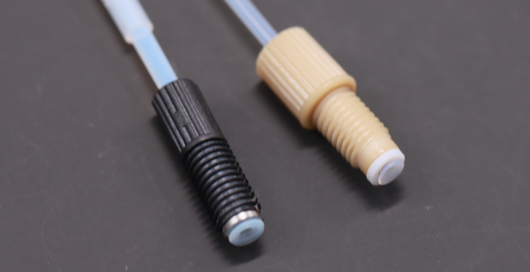
- Check fitting model, tubing OD, washer specification and receiving-port drawing to rule out mixed parts.
- Inspect the flange for skew, cracks or deformation, and check whether forming or compression has affected the flow passage.
- Check for missing, incorrect or damaged washers, and scratches or foreign matter on the port sealing face.
- Assemble using the specified method; watch for tube twisting as the fitting turns.
- Restore the actual routing, remove insufficient-length tension, tight bends and side loads, then retest under equipment conditions.
If an assembly passes on the bench but leaks after installation, prioritize routing and external loads. If the problem is concentrated at one port, check that end’s component combination and sealing face first. This helps distinguish interface mismatch, part condition and routing effects.
06What installed validation should samples undergo?
| Validation item | What to check |
|---|---|
| Dimensions and assembly | Length datum, components at both ends, port spacing, tool access and installed bends |
| Sealing during operation | Sealing under actual positive or negative pressure, temperature and pressure changes |
| Fluids and cleaning | Changes to tubing, flanges and sealing after exposure to actual reagents and cleaning fluids |
| Maintenance and reconnection | Disassemble and reconnect using equipment-defined methods and cycle counts; inspect flanges, washers and sealing afterward |
| Batch consistency | Check materials, dimensions, appearance, identification and test records against the agreed drawing |
Define test pressure, duration, allowable leakage and reconnection cycles from equipment requirements and the confirmed assembly. A fitting or tubing component rating is not automatically a pressure, life or reuse guarantee for the complete assembly.
07What information is needed for a custom flanged tubing assembly?
When submitting requirements to FOREACH, designate the two ends as A and B and list each fitting, thread, washer and port requirement. Single- or double-ended flanging, tubing length, retainers and labels can be specified for the project; deliverable combinations follow the approved drawings and product documentation.
- Fluid: reagent and cleaning-fluid names, concentrations, temperatures, contact times and operating mode.
- Tubing: FEP or PTFE, ID × OD, color, finished length and measurement datum.
- Ends A/B: fitting series, material, complete thread specification, washer requirements and receiving-port drawings.
- Installation: routing, port spacing, bending space and maintenance/removal method.
- Identification: retainers if required, label content, print orientation and installation position.
- Acceptance: dimensional tolerances, appearance, cleanliness, operating sealing and maintenance/reconnection checks.
For replacement projects, include photographs of the original assembly and describe the problem, such as insufficient length, difficult installation, leakage after maintenance or batch variation. Relating the problem to structure and operating conditions helps determine whether to change tubing, fittings, washers or manufacturing and assembly requirements.
08Frequently asked questions
Can I stop a leak by tightening the fitting further?
First check port compatibility, flange damage, washer selection and tube tension or twisting. More force can deform a plastic flange or damage threads. Follow the model-specific assembly method and torque requirement; there is no single value for all flat-bottom fittings. Do not assume thread adhesive or PTFE tape is an appropriate leak fix.
Why does an assembly leak in the instrument after passing a static check?
A static check does not cover every installed condition. Routing can introduce tension, twisting or movement-related side loads; temperature and pressure changes can also affect sealing. Record where and when leakage occurs, inspect length, supports and movement allowance, then retest at actual positive or negative pressure, temperature and duty cycle.
Can a deformed flange be reused or reformed on site?
Do not compensate for cracks, skew or permanent deformation by tightening further. Replacement or reforming must follow the confirmed material, tooling, process, finished length and acceptance requirements. Inspect the passage and sealing again after rework. No universal reuse count applies to every configuration.
How should compatibility be checked after a reagent or cleaning-fluid change?
Identify the actual wetted tubing, flange and other component materials. Check the new fluid’s identity, composition, concentration, temperature, contact time and cleaning procedure. Body material or color does not identify every wetted material, and a generic acid/alkali resistance label is insufficient. Assess the specific material–fluid combination and validate samples under target conditions when needed.
Why can a tight bend affect both flow and sealing?
Bending or crushing can restrict the passage, while insufficient length, twisting and side loads can change the force on the flange face. Check flow restriction and connection loads separately. Confirm bending space, supports and movement allowance for the actual tubing material and dimensions, rather than applying one bend-radius multiple to every tube.
Can all four series share pressure, temperature and tightening-torque limits?
A shared thread or similar shape does not establish shared limits. Body material, tubing and wall thickness, washer, forming process, receiving port and operating conditions all affect the complete assembly. The dimension table checks mounting geometry; confirm allowable pressure, temperature, torque and maintenance cycles for the specific combination and validation conditions.