
What Is a Compression-Ring Fitting? Design, Sizes and Selection
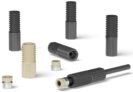
A compression-ring fitting is a flangeless threaded connection for instrument fluidics. It consists of a fitting nut, a compression ring and a sealing ferrule. After square-cutting the tubing, the matched ring and ferrule are preassembled on the end. The nut then loads this assembly against the receiving port to make the seal. Applications include reagent transfer, sample handling and wash lines linking tubing to pumps, valves and fluidic modules in analytical instruments and laboratory automation.
FOREACH HSF6 compact fittings are available with M6×1 and 1/4-28 UNF threads. The configurations covered here accept 1.6, 2.0, 2.5, 3.0 and 3.2 mm OD tubing. Nut materials include PPS and PEEK; the CL-1S kit combines a stainless-steel compression ring with a PEEK sealing ferrule. The illustrated HSF6 has a 6.0 mm head diameter and a 20.0 mm overall length. Use these dimensions to assess port spacing and axial clearance. Thread, tubing-size and material combinations are listed below.
These connections support on-site assembly and prefabricated tubing assemblies with specified lengths, end fittings and identification labels. Complete tubing ends can be disconnected and reconnected for maintenance as specified. This article focuses on HSF6/CL-1S and separately describes CL-1X-16 for smaller 6-40 UNF connections. Select other series and sizes against their own drawings.
01What is a compression-ring fitting? Nut, ring and ferrule
| Component | Function | Selection criteria |
|---|---|---|
| Threaded fitting nut | Screws into the instrument port and applies axial load to the tubing-end kit | Thread, tubing clearance, nut material and external dimensions |
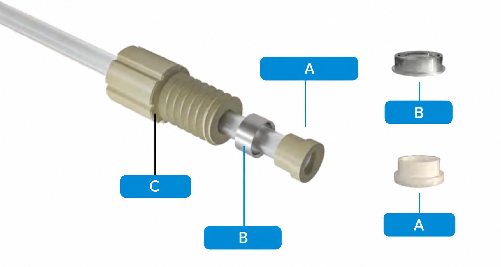
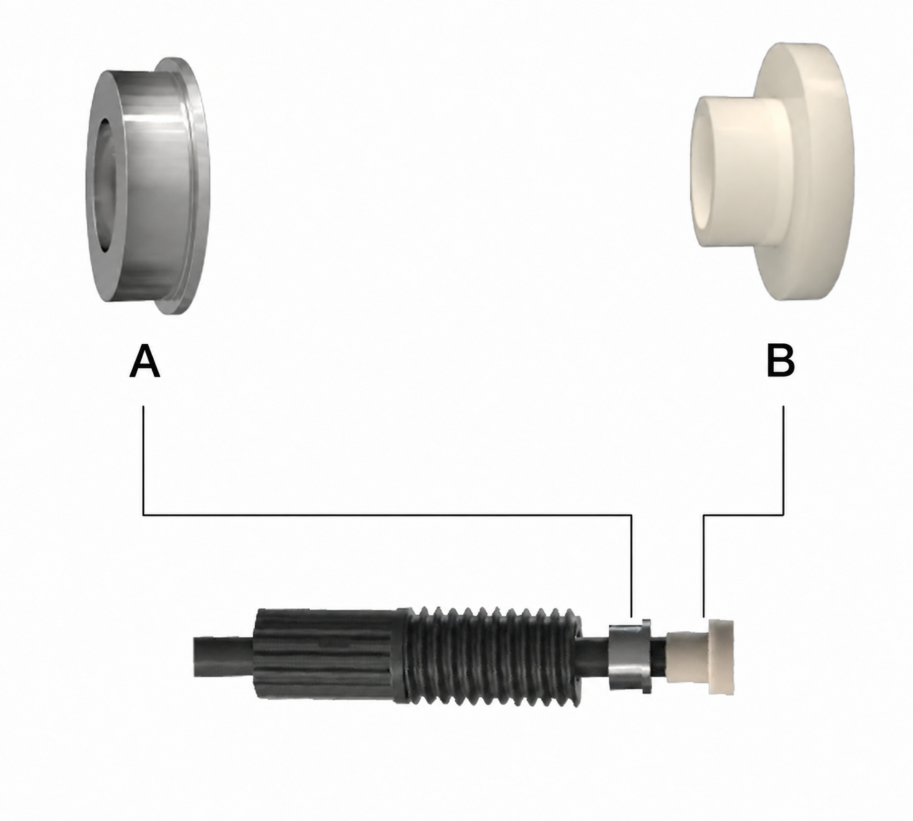
| Compression ring | Fits around the mating portion of the ferrule to compress and retain the tubing-end assembly | Select with the matching ferrule; check orientation and preassembly requirements |
| Sealing ferrule | Mates with the tubing and port to form the front sealing interface | Tubing OD, material, end face and position |
| Tubing and receiving port | Form the flow path and mating sealing surfaces | Tubing ID/OD, cut quality, port bottom and installation depth |
In CL-1S, the compression ring is SUS stainless steel and the sealing ferrule is PEEK. The nut, ring and ferrule are separate components. A PEEK or PPS nut does not mean all wetted surfaces in the connection use that material.
02How does it seal, and why use prefabricated tubing?
As the nut screws into a flat-bottom receiving port, it transfers axial force to the ring and ferrule. Compression at the specified position brings the tubing-end assembly against the port sealing surface. Both ring-to-ferrule fit and tubing-end position matter. The thread provides retention and load; correct contact at the sealing interface must be checked.
Check that the tubing end is flush with the ferrule face
| Tubing-end position | Possible effect | Assembly check |
|---|---|---|
| Flush with the ferrule face | Provides the specified end position | Square, clean cut; position maintained after pressing |
| Recessed inside the ferrule | May leave extra space at the connection | Check cut length and tubing movement during preassembly |
| Protruding or cut at an angle | May contact the port prematurely and interfere with sealing | Recheck end preparation and assembly position |
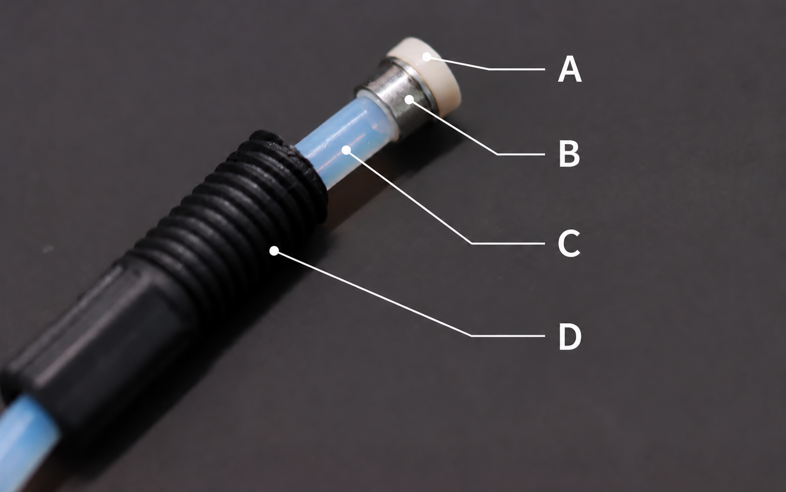
The photograph below identifies the fitting nut, tubing, stainless-steel compression ring and sealing ferrule, showing how the components fit together.
Prepare the tubing end before connecting the instrument
Specify tubing, length, end components and labels before prefabrication. Completing the ends first supports batch assembly and line identification. During connection, the nut can rotate relative to the tubing, reducing twist caused by tightening. This is not a rotary union for continuous rotation during operation.
A serviceable complete tubing-end assembly can be retained during maintenance, but inspect the ferrule face, ring position and tubing condition. Reconnecting an intact end is different from removing an old ring and fitting it to new tubing.
03HSF6 threads, tubing sizes, materials and dimensions
| Complete fitting model | Thread | Compatible tubing OD | Nut material |
|---|---|---|---|
| HSF6-M6-16-PS-B | M6×1 | 1.6 mm | PPS |
| HSF6-M6-32-PS-B | M6×1 | 2.0, 2.5, 3.0, 3.2 mm | PPS |
| HSF6-U28-16-PK-N | 1/4-28 UNF | 1.6 mm | PEEK |
| HSF6-U28-16-PS-B | 1/4-28 UNF | 1.6 mm | PPS |
| HSF6-U28-32-PK-N | 1/4-28 UNF | 2.0, 2.5, 3.0, 3.2 mm | PEEK |
| HSF6-U28-32-PS-B | 1/4-28 UNF | 2.0, 2.5, 3.0, 3.2 mm | PPS |
One nut size can require several different tubing kits
| Actual tubing OD | HSF6 nut size code | Ring-and-ferrule kit | Kit materials |
|---|---|---|---|
| 1.6 mm | Size 16, M6/U28 | CL-1S-16 | SUS ring + PEEK ferrule |
| 2.0 mm | Size 32, M6/U28 | CL-1S-20 | SUS ring + PEEK ferrule |
| 2.5 mm | Size 32, M6/U28 | CL-1S-25 | SUS ring + PEEK ferrule |
| 3.0 mm | Size 32, M6/U28 | CL-1S-30 | SUS ring + PEEK ferrule |
| 3.2 mm | Size 32, M6/U28 | CL-1S-32 | SUS ring + PEEK ferrule |
For 2.5 mm OD tubing in an M6 flat-bottom port, start by checking HSF6-M6-32-PS-B with CL-1S-25. The code 32 identifies this nut size group. The kit must still be size 25 for 2.5 mm tubing; do not choose CL-1S-32 simply to match the nut code.
CL-1X-16 is a separate small-port configuration
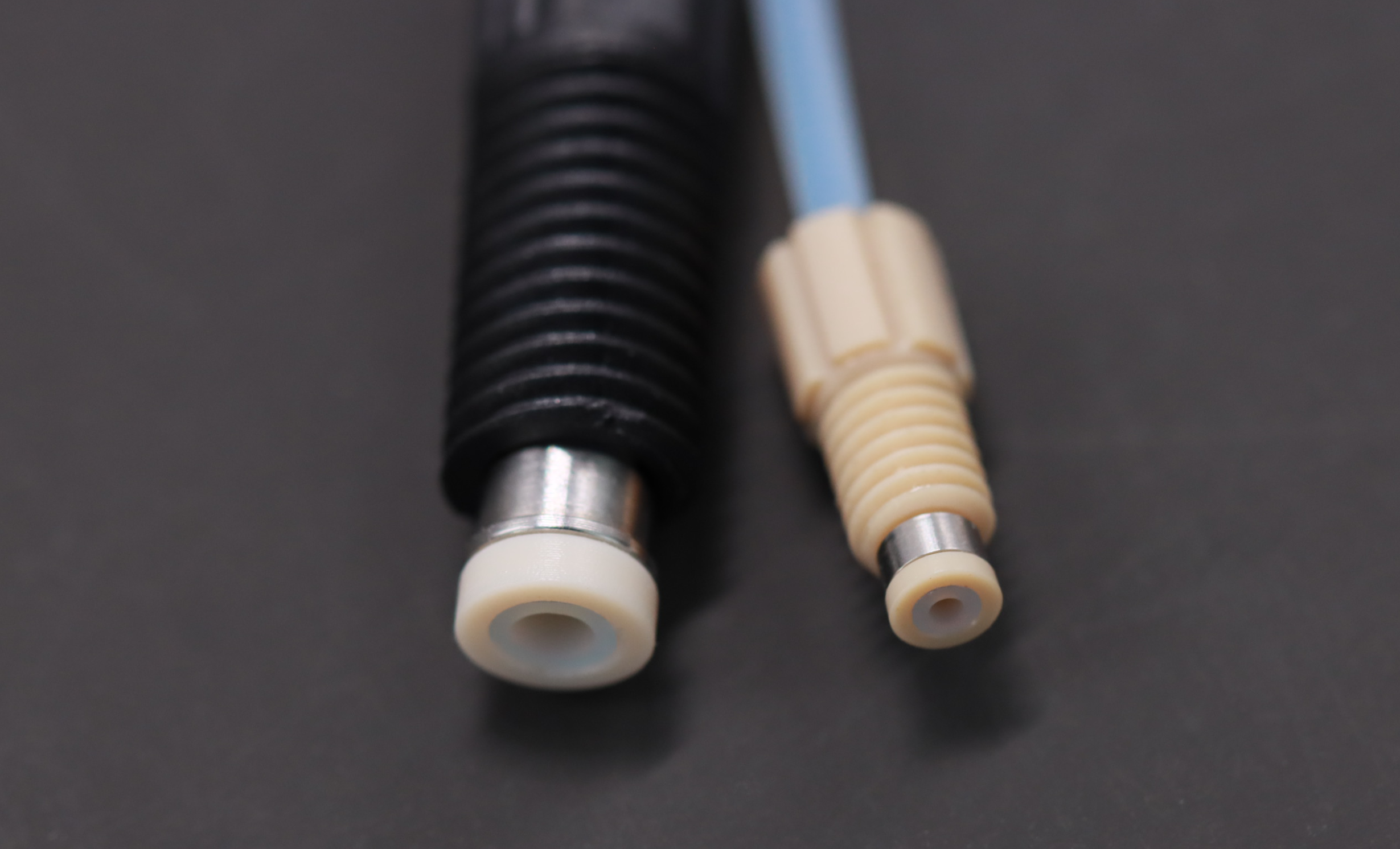
CL-1X-16 accepts 1.6 mm OD tubing and uses a SUS ring with a PEEK ferrule. Its matching fitting is HFL6-U40-16 with a 6-40 UNF thread. Although it accepts the same tubing OD as CL-1S-16, the port, kit geometry and fitting differ; they are not directly interchangeable.
External dimensions determine clearance; installation depth also depends on the port
| Illustrated HSF6 dimension | Value | Use during installation |
|---|---|---|
| Head diameter | 6.0 mm | Check adjacent fitting spacing and access for tightening |
| Overall nut length | 20.0 mm | Combine with installation depth to determine exposed length |
| Axial dimension of the front section | 10.5 mm | Check with port depth and kit position; not effective thread engagement or actual installation depth |
These dimensions describe the illustrated HSF6, not HSF, HFL6 or other configurations. The assembly must reach its sealing position while retaining adequate thread engagement. If the nut bottoms against the instrument surface before the ferrule seats, additional torque will not correct the dimensional mismatch.
04Choosing between compression-ring, ferrule and flanged fittings
| Comparison | Compression-ring connection | Conventional flangeless ferrule connection | Flanged connection |
|---|---|---|---|
| End preparation | Square-cut, then install ring and ferrule | Square-cut, then fit the ferrule | Preform a tubing flange |
| Main components | Nut, compression ring and sealing ferrule | Nut and ferrule | Nut, tubing flange and matching washer |
| Assembly focus | Preassemble with dedicated pliers; check orientation, flush end position and pressing | Correct ferrule, orientation and tubing seating | Flange quality and sealing-face contact |
| Maintenance | Inspect the complete tubing end before reconnecting as specified | Prepare replacement ferrules for the single-installation types covered in the companion article | Inspect flange, washer and port before reconnecting |
| Situations to evaluate first | Prefabricated tubing and maintenance retaining the assembled end | Flangeless assembly with accessible ferrule replacement | Established flanging process or prefabricated flanged assemblies |
These are assembly differences, not pressure rankings. For frequent maintenance, compare inspection and replacement requirements. For closely spaced ports, compare nut dimensions and tool access instead of selecting by connection name alone.
05Applications and tubing-assembly configuration
| Application | Purpose of a tubing assembly | Configuration priorities |
|---|---|---|
| Reagent transfer in analytical instruments | Prepare connections and lengths before instrument installation | End ports, wetted materials, tubing ID and length |
| Sample handling and wash lines | Control end position and simplify line identification and servicing | End gaps, cleaning conditions, carryover requirements and labels |
| Connections between pumps, valves and fluidic modules | Standardize assembly and spare parts | Port spacing, tubing direction, pressure pulsation and support |
| Modules removed for maintenance | Retain and reconnect the complete tubing-end assembly | Expected reconnection frequency, sealing-face inspection and replacement rules |
FOREACH assemblies can use FEP or PTFE tubing with specified lengths and labels. OD determines nut and kit compatibility; ID and length affect flow resistance and internal volume. Tubing with the same OD but different IDs can behave differently in flow and after pressing.
For selection, provide both port drawings, tubing ID/OD, finished length and measurement reference, fluid and cleaning conditions, temperature, continuous and peak pressures, and maintenance requirements. Select each end separately if the ports differ. O-rings or stop sleeves on the tubing limit nut travel; they are not the instrument-port seal.
06Installation, pressure capability and tightening
Separate initial preassembly from connection to the port
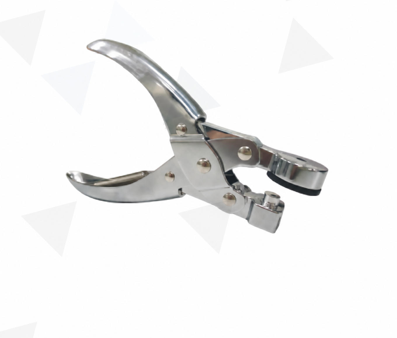
Initial assembly requires the dedicated compatible pliers to press the compression ring and sealing ferrule into position. Hand pressure alone is unlikely to assemble them correctly. Tightening the nut or increasing port torque cannot replace preassembly. For maintenance reconnection, inspect the already assembled tubing end before inserting it into the port.
FOREACH assembly pliers are model T-SF-4-SS, product code 959016. When assembling tubing yourself, obtain the tool compatible with the kit and tubing size and confirm clamping position and operating instructions.
- Cut the tubing square: use a suitable cutter, remove debris and check for flattening, burrs or cracks.
- Check orientation: slide on the nut, ring and ferrule in order, following the selected kit diagram.
- Position and preassemble: align the tubing end flush with the ferrule face, press with the dedicated compatible assembly pliers, then check ring seating and tubing recession or protrusion.
- Connect the port: clean and inspect the sealing surface, hold the assembly in position and tighten as specified.
- Check the connection: secure the tubing and test for leakage, air ingress and end movement at the specified fluid, temperature and pressure conditions.
What pressure can the fitting withstand?
Pressure capability applies to the complete nut, kit, tubing and port combination at stated temperatures and operating conditions. No common HSF6/CL-1S pressure rating is assigned here. Obtain the allowable working pressure for the selected combination. Check positive pressure, vacuum and start/stop peaks separately; a PEEK nut or metal ring alone does not establish pressure capability.
What installation torque is recommended?
| Thread size | Applicable fitting | Recommended installation torque |
|---|---|---|
| M6×1 | Plastic rigid-tubing fitting | 0.25–0.30 N·m |
| 1/4-28 UNF | Plastic rigid-tubing fitting | 0.25–0.30 N·m |
| 6-40 UNF | Plastic U40 compression-ring fitting | 0.08–0.15 N·m |
These values apply to threaded tightening into the port, not the pressing force for kit preassembly. Preassemble the ring and ferrule correctly, tighten to the corresponding torque, then check sealing and tubing-end position.
Reconnection and troubleshooting
| Symptom | Check first | Action |
|---|---|---|
| Leakage after first connection | Matched parts, pressing orientation, flush tubing end and port bottom | Stop and depressurize; correct positioning or component problems and retest |
| Leakage after maintenance reconnection | Dirty or damaged ferrule face, ring movement or tubing deformation | Determine whether cleaning, repositioning or assembly replacement is needed |
| Reduced flow after assembly replacement | Tubing ID, length, debris, end compression and tight bends | Compare flow and pressure drop with the same fluid and pump conditions |
| Passes static check but fails during operation | Start/stop peaks, temperature changes, vibration and external loads | Check support and movement allowance; validate under actual operating cycles |
Reconnection as specified does not mean unlimited cycles or maintenance-free use. For frequent disconnection, define test cycles, operating conditions and allowable leakage. Record sealing, tubing-end position and flow after each cycle. Address worn faces, cracks or ring movement according to the assembly requirements.
07Frequently asked questions
Is a compression-ring fitting also flangeless?
Yes. The ring-and-ferrule design described here uses square-cut tubing without a preformed flange. Conventional ferrule fittings can also be flangeless, but parts and assembly differ; the name alone does not establish interchangeability.
If the HSF6 model has size code 32, must the kit also be size 32?
No. The size-32 HSF6 nuts listed here cover tubing ODs of 2.0, 2.5, 3.0 and 3.2 mm, while CL-1S is selected for the actual OD. For example, 2.5 mm tubing needs CL-1S-25. Nut size group and kit tubing size are separate selections.
Are CL-1S-16 and CL-1X-16 interchangeable?
No. Both accept 1.6 mm OD tubing, but CL-1S corresponds to the HSF6 M6/U28 configurations here, while CL-1X-16 pairs with HFL6-U40-16 for a 6-40 UNF connection. Check nut, port and kit geometry together.
Is a dedicated assembly tool required?
Yes. Initial kit preassembly requires compatible dedicated pliers: FOREACH T-SF-4-SS, product code 959016. Hand pressure alone is unlikely to seat the ring and ferrule correctly, and higher nut torque cannot replace preassembly. Check tool compatibility with the kit and tubing size. Inspect complete, previously assembled ends before reconnecting.
What torque should be used for installation?
FOREACH plastic rigid-tubing fittings with M6×1 or 1/4-28 UNF threads use 0.25–0.30 N·m; plastic U40 compression-ring fittings with 6-40 UNF threads use 0.08–0.15 N·m. These recommendations apply to threaded port tightening, not kit preassembly force.
Does reconnection mean an old ring can be transferred to new tubing?
Not necessarily. Inspect sealing surfaces, ring position and tubing condition before reconnecting an intact end. Removing an old ring and installing it on another tube is a separate operation; permission depends on the specific kit requirements.
Does a flush tubing end guarantee zero dead volume?
No. A square cut and correct end position help control gaps, but residual volume also depends on port geometry, tubing ID and assembly condition. Assess sample and wash lines against carryover and cleaning requirements.