
What Is a Flangeless Ferrule Fitting? Design, Sizes and Selection
A flangeless ferrule fitting is a threaded connection for rigid microfluidic tubing. The terms flangeless fitting and ferrule fitting emphasize different features: no preformed tubing flange is needed, and a separate ferrule provides gripping and sealing. Tightening the nut compresses the ferrule around the tubing and against the receiving port. These connections can link tubing to pumps, valves and fluidic modules in reagent transfer, sample handling and wash lines.
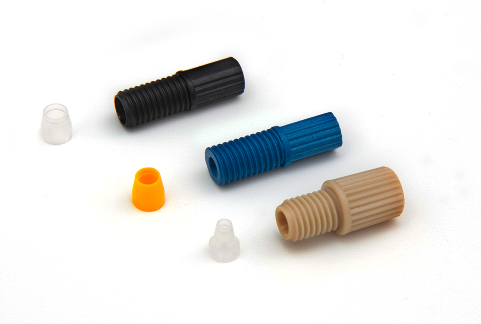
FOREACH offers four series: HN, HN6, HNF and HNF6, with standard knurled and compact head styles. They cover tubing ODs of 1.6, 2.0, 2.5, 3.0 and 3.2 mm and M6×1 or 1/4-28 UNF flat-bottom ports. For example, the illustrated HN6 has a head diameter of 6.4 mm and an overall length of 15.5 mm; check the dimensional drawing for each other series.
HN and HN6 nuts are available in PEEK, PVDF, POM and PPS; HNF uses PVDF and HNF6 uses PPS in the configurations discussed here. Separate ferrules are available in PP and ETFE. Select the nut and ferrule together for the tubing OD, fluid and installation space, and confirm the exact materials and dimensions by part number.
01What is a flangeless ferrule fitting?
This article covers threaded microfluidic fittings with a separate ferrule. Tubing passes through the nut and ferrule into the instrument port; tightening the nut applies axial compression. The ferrule is the sealing and gripping part around the tubing, not a hose clamp or a sanitary clamp connection.
| Component | Function | What to check |
|---|---|---|
| Threaded nut | Engages the instrument port and transmits force to the ferrule | Series, thread, bore, material and installation clearance |
| Ferrule | Grips the tubing and participates in sealing under compression | Part number, tubing OD, material, orientation and assembly requirements |
| Tubing | Carries the fluid; its outer wall contacts the ferrule | ID, OD, OD tolerance, material, wall thickness and cut quality |
| Receiving port | Provides the threaded interface and sealing seat | Thread, bottom geometry, depth and sealing-surface condition |
The HN, HN6, HNF and HNF6 configurations discussed here use M6×1 or 1/4-28 UNF flat-bottom ports. Other geometries, threads and dedicated high-pressure fittings require their own drawings and assembly instructions.
02How does the connection seal?
Slide the correct nut and ferrule onto square-cut tubing in the specified orientation. Insert the assembly into the matching port while keeping the tube end in its required position. As the nut advances, it applies axial force to the ferrule, which grips the tubing and seals against the port. Sealing depends on the components seating correctly, not on thread friction alone.
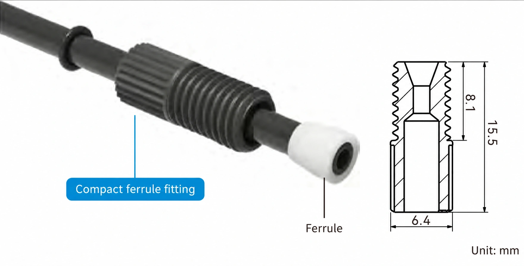
If the tube end moves, the ferrule is reversed or the tubing OD is wrong, tightening resistance may increase before the sealing surfaces are seated. Additional force does not correct this mismatch and may deform the ferrule or tubing.
Check thread engagement separately from correct seating of the ferrule, tube and port. M6×1 and 1/4-28 UNF are different threads; being able to start a few turns does not prove compatibility. Do not use thread tape or sealant to compensate for a mismatched sealing geometry.
03HN, HN6, HNF and HNF6: thread length and installation space
These FOREACH series differ in head style, material, threaded-section length, overall length and ferrule configuration. Even when thread designation and tubing OD match, compare the dimensions needed for the complete connection.
A 2.4 mm difference in threaded-section length: what must fit?
| Series | Head style | Threaded-section length | Overall length |
|---|---|---|---|
| HN | Standard knurled | 8.1 mm | 18.1 mm |
| HN6 | Compact | 8.1 mm | 15.5 mm |
| HNF | Standard knurled | 10.5 mm | 16.5 mm |
| HNF6 | Compact | 10.5 mm | 20.0 mm |
This difference does not mean that HNF or HNF6 necessarily installs 2.4 mm deeper in the same port. Installed depth also depends on the port and ferrule seating positions. Effective thread engagement is the length over which the internal and external threads actually mate after assembly. Confirm the tube-end position separately.
The nut must compress a correctly seated ferrule while maintaining the thread engagement required by the design. If a shoulder contacts the equipment surface before the ferrule is compressed, the nut may feel fully tight while the joint still leaks. Check the dimensional fit; more torque cannot correct an axial mismatch.
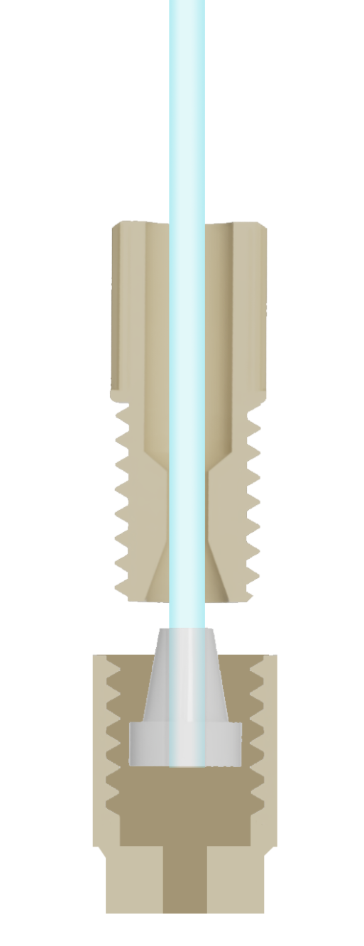
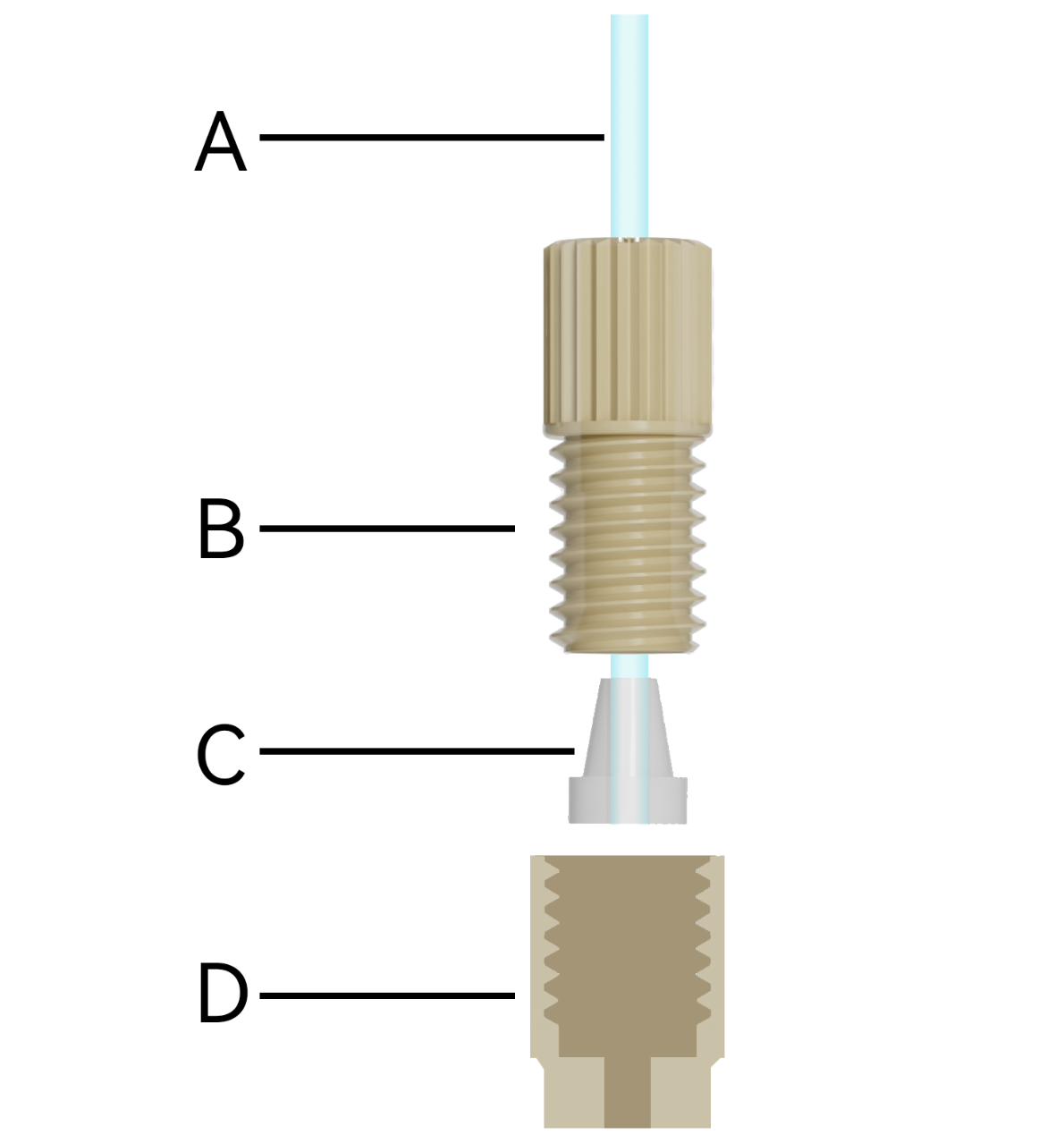
The section and exploded views show the relative positions of the nut, ferrule, tubing and port. They explain the connection layout, not the dimensions or installed depth of every model in the table. Use the corresponding drawing for dimensional checks.
Compare head style and overall length separately
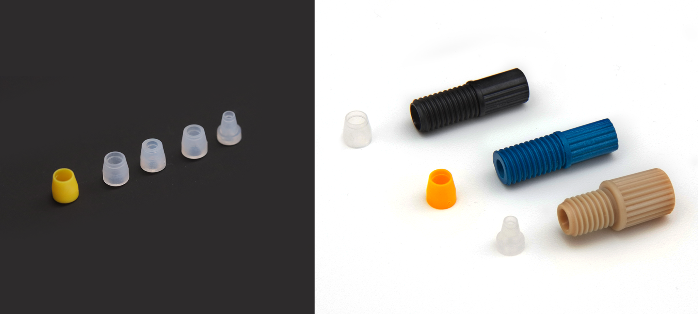
Overall length helps assess axial space, but installed protrusion also depends on insertion depth. HN6 is 15.5 mm long versus 18.1 mm for HN. HNF6 has a compact head yet is 20.0 mm long, compared with 16.5 mm for HNF. For closely spaced ports, compare head diameter; for limited axial clearance, compare overall length, installed protrusion, tightening access and tubing routing.
Then check tubing size groups, materials and ferrules
| Series | Head style and nut materials | Tubing-size selection |
|---|---|---|
| HN | Standard knurled; PEEK, PVDF, POM or PPS | Nut size groups: 1.6 mm and 2.0–3.2 mm; select a ferrule for the actual tubing OD |
| HN6 | Compact; PEEK, PVDF, POM or PPS | As with HN, distinguish the nut size group from the exact ferrule OD size |
| HNF | Standard knurled; representative available models use PVDF | Select by individual tubing OD: 1.6, 2.0, 2.5, 3.0 or 3.2 mm |
| HNF6 | Compact; representative available models use PPS | Select by individual tubing OD: 1.6, 2.0, 2.5, 3.0 or 3.2 mm |
For example, the HN and HN6 “32” nut size group covers tubing ODs of 2.0, 2.5, 3.0 and 3.2 mm. This does not mean one ferrule fits all four sizes. A 2.5 mm tube still needs a ferrule sized for 2.5 mm OD. HNF and HNF6 use individual tubing-OD configurations rather than the HN grouping rule.
Confirm the complete ferrule part number
HN and HN6 use CL-0X ferrules in OD sizes coded 16, 20, 25, 30 and 32. CL-0 and CL-0X have different geometries; the same “25” size code does not make them interchangeable. For HNF and HNF6, confirm the ferrule against the complete nut part number and approved component list before ordering or assembly.
Select nut and ferrule materials separately. PP and ETFE ferrule options must be confirmed by complete part number. A PEEK or PVDF nut does not mean all wetted surfaces in the connection have that material, and color is not a substitute for material identification.
04How does a ferrule connection differ from a flanged connection?
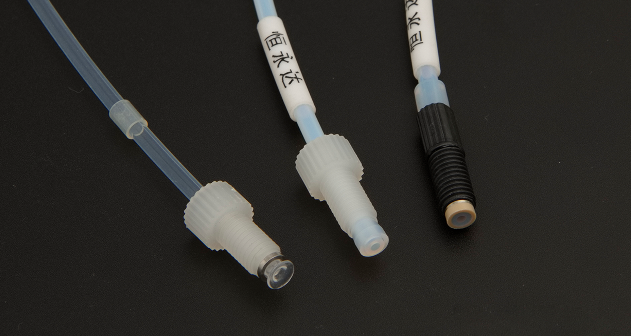
| Comparison | Ferrule connection | Flanged connection |
|---|---|---|
| Tube preparation | Square-cut, clean tube end; no preformed flange | Form the tube-end flange for the specified material and size |
| Sealing interfaces | Tubing, ferrule and receiving port | Tube-end flange, matching washer and flat-bottom port |
| Assembly checks | Ferrule series and size, orientation and tube-end position | Flange quality, washer configuration and sealing-face contact |
| Maintenance | Replace the ferrules covered here according to their single-installation requirement | Inspect flange, washer and port according to the assembly requirements |
| Interchangeability | Check the whole assembly, not just thread and tubing size | Also check the port and all mating components |
A flanged design may suit an established flange-forming process or prefabricated tubing assemblies. A ferrule design may suit workflows that avoid flange forming and allow ferrule replacement during maintenance. Permitted pressure, long-term sealing and reconnection limits must come from the specific assembly specifications and validation.
Further reading: Flanged tubing assemblies: design and selection
Compression-ring connections can also avoid tube-end flanging, but their sleeves, washers and assembly method differ from the ferrule arrangement described here. “Flangeless” does not identify one universal sealing structure. See the rigid-tubing fitting guide for a comparison of the three designs.
Rigid-tubing fittings: flanged, ferrule and compression-ring connections
05How to select a suitable fitting
Start with the port, then select tubing size and components
Obtain the complete port thread specification and section drawing to establish the sealing geometry. Use the actual tubing OD to select the nut and ferrule. Tubing ID and length determine internal volume, flow resistance and flow requirements. The nut through-bore is a tubing clearance dimension, not automatically the fluid-path ID.
For a 2.5 mm OD tube with HN6, select the appropriate nut size group and a CL-0X-25 ferrule, then verify the thread, nut material, ferrule material and tubing tolerances. This identifies a candidate assembly; pressure capability, chemical compatibility and installed sealing still require confirmation.
Match materials to the actual fluid and operating conditions
Specify fluid composition, concentration, operating temperature, exposure time and cleaning procedure. Check tubing, ferrule and all wetted components. Also check whether the tubing wall retains its bore and grip under assembly compression. Chemical resistance alone does not validate every wall thickness, OD tolerance or ferrule combination.
Check installation and maintenance access
| Information to provide | What it establishes |
|---|---|
| Port thread and section drawing | Correct engagement and sealing position |
| Tubing material, ID, OD and OD tolerance | Dimensional fit and gripping compatibility |
| Fluid, concentration, temperature and cleaning conditions | Wetted-material compatibility and service conditions |
| Continuous and peak pressure, vacuum and start/stop duty | Actual loads and validation conditions |
| Port spacing, axial clearance and tubing direction | Space for installation, tightening, routing and removal |
| Maintenance frequency and replacement method | Spare parts and suitability of the connection design |
06Installation and service considerations
Use a tubing cutter suitable for the material to obtain a square end. Remove debris and check for flattening, scratches or deformation. Confirm ferrule part number, orientation and tube-end position, then keep the assembly seated while tightening as specified. Use the method and torque confirmed for that configuration; there is no universal torque for all plastic fittings.
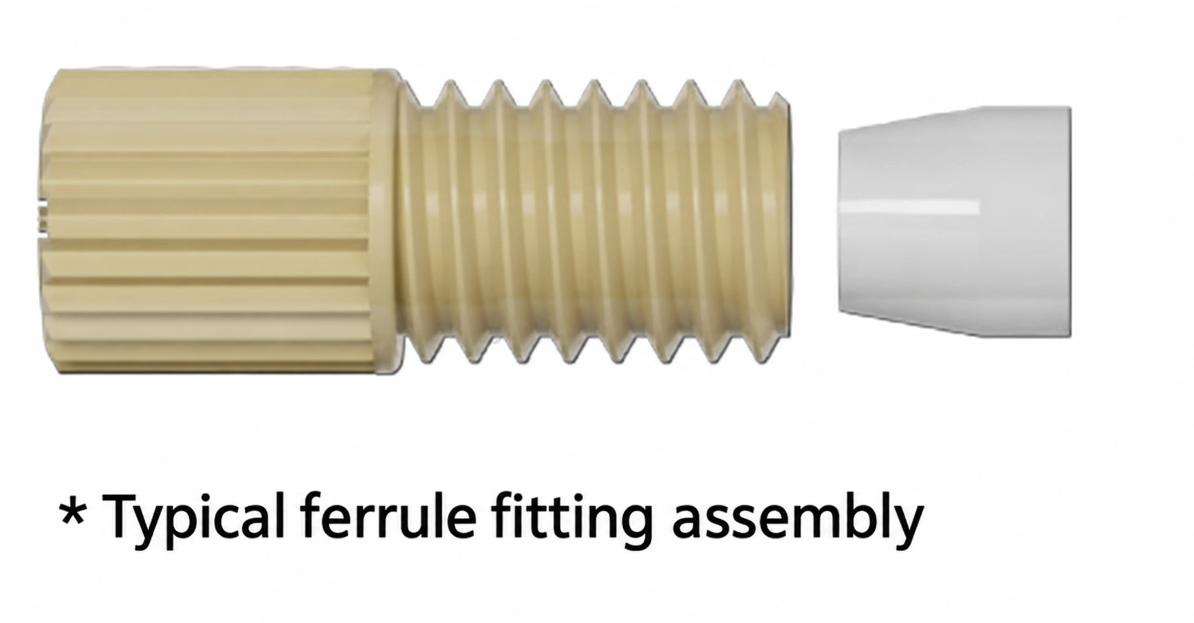
Identify the cause before changing the assembly
| Symptom | Check first | Action and verification |
|---|---|---|
| Leak after tightening | Port compatibility, ferrule size and orientation, tube seating | Stop and depressurize, inspect, replace damaged parts and retest |
| Lower flow after changing the fitting | Cutting debris, tube compression, different ID or tight bends | Compare flow and pressure drop at the same fluid, tube length and pump conditions |
| Passes a static check but leaks in operation | Start/stop pressure peaks, temperature change or tubing loads | Check supports and slack; validate under actual operation |
| Leaks after reassembly | Used-ferrule deformation, tube-wall damage or port contamination | Prepare a new ferrule for single installation; inspect tubing and reassemble |
These symptoms guide troubleshooting; they do not prove a cause. For example, reduced flow may come from a different tubing ID, cutting debris or bends rather than the fitting type. Compare under controlled conditions to see whether assembly or size changes solve the problem.
Separate ferrule replacement from nut reuse
The ferrules covered here are specified for a single installation; reinstalling them may cause irreversible deformation. Prepare matching new ferrules for maintenance. Inspect the gripped tube end and rework it if required. Assess nut reuse separately by inspecting its threads and load-bearing surfaces; replacing the sealing component does not automatically mean replacing the whole fitting.
Validate the complete connection in the fluidic system
Check leaks, tube movement and flow under defined fluid, temperature and pressure conditions; check air ingress on suction lines. Then cover actual start/stop cycles, pulsation, temperature changes and motion, recording test duration, cycles and allowable leakage. A static pressure-hold pass applies only to those test conditions, not full instrument operation.
Permitted pressure depends on the complete nut, ferrule, tubing and port combination. Do not transfer a dedicated high-pressure fitting rating to HN, HN6, HNF or HNF6. A stronger nut material alone does not increase the allowable pressure of the entire fluid path.
07Frequently asked questions
Are flangeless fittings always tool-free?
No. Hand tightening, a dedicated driver and torque-controlled tools are configuration-specific. Flangeless means that no tube-end flange is preformed; it does not guarantee that every model can be installed by feel alone.
Are CL-0 and CL-0X interchangeable at the same tubing OD?
Not on OD alone. Their geometries differ and must match the nut and port. Confirm complete part numbers and the approved component combination; trial tightening or extra force does not establish compatibility.
Do compact fittings withstand more pressure than standard knurled fittings?
Head style does not determine pressure capability. Compact heads concern installation space; permitted pressure also depends on ferrule, tubing, port, temperature and assembly conditions. Check and validate the specific combination.
Does tubing ID matter when both tubes have 1.6 mm OD?
Yes. OD matches the nut and ferrule, while ID affects flow resistance, internal volume and wall thickness. Confirm how the tube wall behaves under compression as well as the actual flow, pressure and fluid requirements.