
Inkjet Printer Pumps: Micro Diaphragm Pumps for Stable Ink Supply
Engineers working with inkjet equipment are familiar with blurred printing, stray ink droplets and broken lines. The first reaction on site is often to change the ink or clean the printhead. Troubleshooting should also include ink-path pressure: its stability depends on the pump's actual output, flow resistance and coordination with the control system. A micro diaphragm pump is an easily overlooked part of that circuit.
UV Ink Pumps: Why Ink Viscosity and Flow Resistance Matter
UV ink viscosity varies with formulation and temperature, and some formulations become more viscous at lower temperatures. Where filter and tubing resistance is high, gravity supply alone may not meet demand. The pump must draw ink from the tank and drive it through coarse filtration, fine filtration and tubing toward the printhead supply side. If the delivery pressure difference or working flow is insufficient, replenishment at the printhead cannot keep pace with ink consumption, and broken print lines may become more pronounced.
A diaphragm pump separates the liquid side from the drive without requiring a rotating shaft to pass through a dynamic seal into the wetted chamber. Wetted parts include the pump head, diaphragm, valves and relevant seals. Specific models with self-priming, dry-running or speed-control capabilities can be configured in supply or return branches to suit the equipment. Long-term compatibility with the target UV ink must be confirmed through wetted-material and actual-fluid testing.
| Pump type | Relative characteristics | Limitations to assess |
|---|---|---|
| Gear pump | Relatively steady output for continuous transfer | Assess how pigment particles, working clearances and wear affect output |
| Diaphragm pump | Liquid and drive sides are separated; some models support self-priming, dry running or speed control | Reciprocating operation produces flow pulsation; assess damping and buffering. Capabilities depend on the model |
| Peristaltic pump | Only the tubing contacts the liquid, making the wetted path easy to replace | Tubing is a consumable; fatigue, ageing and compression affect flow and pressure |
Ink Circulation Pumps: Supply Pressure, Meniscus Pressure and Return Flow
An ink circuit involves more than one pressure condition. Positive pressure on the supply side moves ink through filters and tubing; many drop-on-demand printheads use controlled slight negative pressure to maintain the nozzle meniscus. The pressure difference between supply and return sustains circulation, helping reduce pigment stagnation and carry free bubbles toward an air-removal point.
Liquid diaphragm pumps can transfer ink on the supply and return sides, while slight negative pressure at the nozzles is established by the complete fluid circuit and pressure-control arrangement. Supply pressure, printhead meniscus pressure and the supply-to-return pressure difference are related but are not the same value. A pump's rated pressure must not be used directly as the printhead setting.
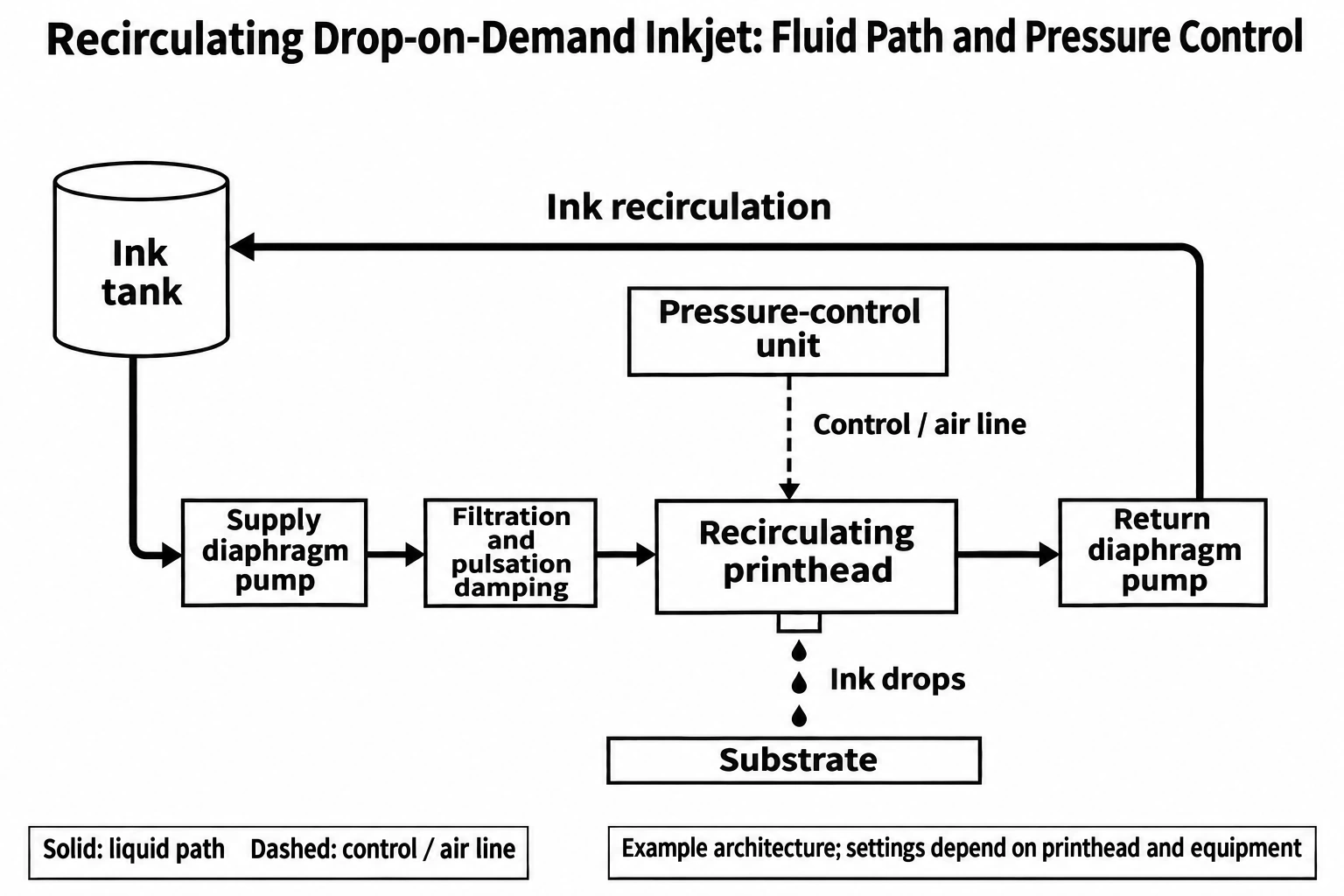
The allowable negative-pressure range and fluctuation limits depend on the printhead, ink and operating conditions. Pressure outside those requirements may disturb the nozzle meniscus or ink delivery. Check settings against the applicable manual rather than applying a universal rule of thumb.
Diaphragm Pump Pulsation and Cavitation Risks in Inkjet Systems
The first issue is pulsation. A diaphragm pump's reciprocating mechanism produces flow pulsation, and inkjet circuits can be sensitive to pressure fluctuations. Accumulators, dampers or other buffering measures therefore need evaluation to keep fluctuation at the printhead within its limits. Measure the actual pressure response rather than relying on an average reading, and do not treat one fixed fluctuation value as a universal standard for every printhead.
The second group of issues occurs on the inlet side. Inadequate ink supply upstream of the pump or entrained gas may cause reduced flow, continuous bubbles or a gurgling noise. Check the ink-tank level and inlet tubing before continuing to adjust control-panel settings. Air ingress, dissolved gas coming out of solution and cavitation are different phenomena. Establishing whether cavitation is occurring also requires consideration of inlet pressure, ink temperature and volatility.
Inkjet Printer Pump Troubleshooting: Check the Ink Path First
Check ink supply first: the pump, liquid level, filters and tubing. Next check for air ingress and proper air removal, then inspect the printhead, and finally review pressure settings against the equipment requirements. When the circuit contains continuous bubbles or a restriction, adjusting pressure alone often fails to identify the cause. For leak checks or a static pressure-hold test, use the pressure, duration and allowable drop specified by the equipment. Change only one variable at a time.
The table lists common field symptoms and the checks to prioritise. It helps narrow the investigation; a symptom alone is not enough to diagnose pump or printhead failure.
| Symptom | Checks to prioritise | Action to consider |
|---|---|---|
| No ink delivery | Kinked tubing, blocked filter, low ink level or a pump that has not filled with liquid | Restore supply and a clear path, fill and remove air according to the procedure, then measure flow |
| Ink is delivered, but the nozzle-check pattern has missing lines | Nozzle condition, bubbles and replenishment capacity | Check printhead maintenance and ink supply, retaining nozzle-check patterns before and after intervention |
| Pronounced pressure fluctuations | Air ingress, liquid level, pump pulsation and control response | Resolve supply and sealing issues first, then check damping and control |
| Negative pressure keeps drifting in one direction | Return-path restrictions, liquid level, seals and pressure measurement points | Check supply, return and measurement conditions, then inspect pressure control |
| Stray ink droplets or ragged character edges | Printhead condition, ink temperature and viscosity, and meniscus pressure | Assess the nozzle-check pattern together with measured pressure and follow the printhead requirements |
| Faint or pale characters | Actual ink-supply flow, filter pressure loss and printing conditions | Check whether replenishment keeps pace with consumption, restore circuit conditions and retest |
Micro Diaphragm Pump Selection: Materials and Pulsation Control
A diaphragm pump's value in inkjet equipment goes beyond transferring ink: it works with the circuit and control system to maintain suitable delivery, circulation and pressure conditions. Start by checking two priorities: whether the wetted materials suit the target ink system, and whether pulsation suppression meets the printhead's requirements.
The material review covers the pump head, diaphragm, valves and seals, taking account of the concentration, temperature and contact duration of UV, solvent-based or water-based inks and the associated cleaning fluids. Measure pulsation under the actual tubing and printing load. Also check the flow-pressure operating point, inlet conditions and duty cycle, then complete prototype validation with proper air removal and measurement records.
FOREACH Diaphragm Pumps for Ink Supply and Return
FOREACH miniature liquid diaphragm pumps can be evaluated as candidates according to the flow and pressure requirements of the ink circuit. DPL30 and DPL60 address different flow requirements in supply or return branches; DPL30H is a candidate for evaluating an upstream transfer section with higher pressure requirements.
| Candidate model | Free flow | Rated pressure | Circuit role to evaluate |
|---|---|---|---|
| DPL30-DB | 300 mL/min | 100 kPa | Supply, return and circulation sections with a lower flow requirement |
| DPL60-DB | 600 mL/min | 100 kPa | Supply or return sections with a higher flow requirement |
| DPL30H-DS | 300 mL/min | 600 kPa | Upstream transfer with long tubing or high filter resistance; do not use the rated pressure directly to pressurise the printhead |
Free flow and rated pressure describe different specification conditions. They do not mean that free flow is guaranteed at rated pressure. Check the complete parameters, connections and wetted-material combination for the specific model.
The formal specifications for all three series list purified water as the working medium; other liquids require actual customer evaluation. When considering wetted-material configurations involving PPS, EPDM, PTFE or FFKM, validate them against the ink composition, concentration, temperature, contact duration and cleaning fluid. Material names alone cannot establish long-term ink compatibility.