
Why Do Air Bubbles Delay or Bias Piston Pump Dispensing?
A completed piston stroke does not prove that the intended liquid volume reached the vessel. Bubble compression temporarily stores displacement; expansion can then cause a trailing dispense or affect the next cycle. Locate where bubbles first appear and compare synchronized pressure and individual dispense masses before and after priming.
Where does the displaced volume go?
Ideal displacement equals effective piston area times travel. In a real fluid path, gas, flexible tubing and valve cavities can store part of that displacement. Delivered volume is the liquid that actually reaches the target. Short strokes, the first dispense after reversal and restart are particularly sensitive.
For illustration, a sealed 10 μL bubble compressed from 100 to 120 kPa absolute occupies about 8.33 μL under an isothermal ideal-gas assumption. Approximately 1.67 μL is temporarily stored. This is neither measured Foreach error nor a prediction of permanent underdelivery: pressure recovery may release that volume later in the same or a subsequent cycle.
P₁V₁ ≈ P₂V₂; ΔVgas = V₁(1 − P₁/P₂)Order-of-magnitude model for sealed ideal gas, approximately isothermal, without dissolution or mass transfer. Use absolute pressure. ΔVgas is temporary compression volume, not a final underdelivery formula.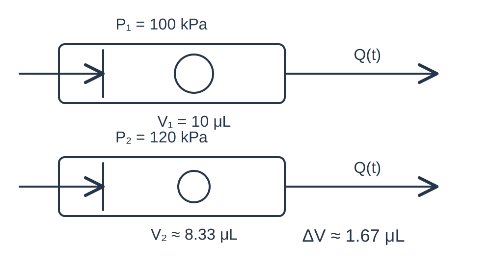
Use location and timing to select a hypothesis
Record whether bubbles first appear upstream, in the chamber, around the valve or near the outlet. Align observations with aspiration, valve switching and dispensing. An observation tube should add minimal dead volume or resistance; clear tubing cannot exclude gas hidden in an opaque chamber.
A low first dispense is not specific to bubbles. Backlash, valve delay and tubing compliance can produce similar results. Stronger evidence requires repeatable improvement when gas conditions change while other variables remain controlled.
| Location or event | Check first | Interpretation limit |
|---|---|---|
| Chamber; first reversal dispense | Priming and pressure establishment | Backlash may also contribute |
| Continuous inlet bubbles | Connections, level and temperature | Ingress and outgassing may coexist |
| Drops after stopping | Gas/tubing storage and valve state | Not necessarily leakage |
| Only the target well is short | Droplet formation and transfer | Keep reference backpressure equivalent |
Separate residual air, ingress and outgassing
Rapid stabilization after controlled priming supports residual air after installation or fluid replacement. Persistent bubbles at an inlet connection suggest checking its seal under suction. An inlet can admit air without showing an external liquid leak.
Warming or local pressure reduction can release dissolved gas. Compare the same fluid before and after degassing at the same temperature, liquid level and pressure conditions. Improvement supports gas involvement; simultaneous temperature or viscosity changes prevent a clean attribution.
Validate priming instead of adding a fixed correction
Hold target volume, temperature, reservoir level, valve timing and outlet load constant. Weigh each dispense and record inlet and outlet pressure. Compare the initial state, controlled priming, extended operation and restart; identify first dispenses separately from steady operation.
Define project-specific priming acceptance using repeatable mass results, pressure traces and observable gas conditions. Neither a universal cycle count nor a fixed extra dispense volume resolves every bubble mechanism. Check whether the original symptom returns during extended operation.
Distinguish pump delivery from droplet transfer
If outlet collection is correct but the target well receives less, inspect hanging drops, splash, tip wetting and transfer timing. Preserve equivalent outlet loading when changing the collection arrangement; removing the tip also changes backpressure.
Where the design permits a pressure-hold test, keep valve position, initial pressure and temperature consistent. Gas expansion, tubing relaxation and internal leakage all influence pressure decay. A decay slope alone cannot identify a failed fitting or valve.
Evaluate the EAS chamber and repeat the complete test
The official Foreach EAS specification describes an easy-deaeration chamber. It is a candidate for reducing trapped air, not a guarantee of bubble-free operation with every fluid, orientation and valve circuit. Confirm capacity, interfaces and the actual valve circuit against the official specification.
The EA-500-PMMA displayed configuration is 500 μL with 2000 full steps, or a theoretical 0.25 μL per step. Resolution does not establish delivered-liquid accuracy. Recheck the real fluid, minimum target volume, first dispense, steady operation and restart. Hamilton's pressure/bubble monitoring material supports the observation approach; it does not imply equivalent sensors are included in Foreach pumps.
Related reading and specifications
Technical references
Frequently asked questions
Do bubbles always reduce every dispense?
No. Compression and expansion can delay delivery, generate trailing liquid or couple successive cycles. Valve state, pressure and collection timing determine the final result.
Is recovery after extra priming sufficient?
Repeat extended operation and restart testing. Persistent ingress or outgassing can recreate the problem; identify the source.
Does high piston pump resolution eliminate bubble error?
No. Geometric displacement resolution cannot remove gas or tubing storage, or ensure complete droplet transfer.
Does EAS guarantee bubble-free operation for all reagents?
No universal guarantee follows from the chamber design. Validate the actual fluid, orientation, valve cavities and priming sequence.