
How Should Piston Pump Aspiration Speed and Dwell Be Set for Viscous Reagents?
A stable aspiration window depends on resistance, filling time and pressure. Test aspiration speed and the subsequent dwell independently, then select a faster combination that satisfies bias, repeatability, bubbles and cycle-time requirements. Water settings do not automatically transfer to the reagent, and completed motion does not prove fluid equilibration.
Relate viscosity and bore to aspiration pressure loss
For fully developed Newtonian laminar flow in a circular tube, pressure loss increases with viscosity and length and depends strongly on the fourth power of bore. A larger main tube may help, but a valve, fitting, filter or needle can remain the narrowest restriction.
This steady relation explains a tube segment, not every chamber transient. Do not directly apply it to shear-thinning, particle-laden or strongly non-Newtonian reagents. Record temperature and rheological conditions and locate restrictions with pressure measurements.
ΔP = 128 μ L Q / (π d⁴)μ: dynamic viscosity; L: length; Q: volume flow; d: internal diameter. Use consistent SI units. Fully developed Newtonian laminar flow in a rigid circular tube; entrance, local-component and transient effects are excluded.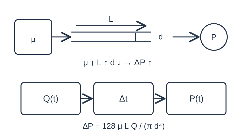
Why can filling continue after the piston stops?
Retraction creates geometric volume that the upstream liquid must fill through a resistance. With gas or elastic tubing present, filling and pressure recovery can continue after motion stops. Immediate valve switching can carry an unsettled state into the next operation.
Choose dwell using pressure recovery and reproducible dispense mass. Tecan guidance supports appropriate speed and delay for viscous fluids, but its platform and tip settings do not establish a universal 200 ms or 500 ms setting for Foreach pumps.
Build a speed-by-dwell test matrix
Within the pump and driver's permitted range, compare low, medium and high aspiration speed with short, medium and long dwell: a 3×3 experiment. Begin conservatively. Keep target volume, dispense settings, reservoir level, valve sequence and backpressure fixed.
For every combination, retain individual masses, mean bias, CV, minimum inlet pressure, bubble observations and complete cycle time. Set repetition count from project uncertainty and acceptance needs. The three levels are experimental factors, not operating recommendations. Revisit the baseline between trials to expose thermal drift.
| Factor | Keep fixed | Record |
|---|---|---|
| Low/medium/high aspiration speed | Dispense, valve sequence, volume | Inlet pressure and bubbles |
| Short/medium/long dwell | Selected speed and fluid path | Individual masses, bias and CV |
| Interleaved baseline repeats | Fluid batch and backpressure | Temperature and trial order |
| Window qualification | Lowest level and temperature limits | Full cycle time and pass rate |
Optimize dispensing and droplet transfer separately
Aspiration is constrained by filling and low-pressure margin. Dispensing also depends on backpressure, splash and droplet detachment. The two speeds need not match. Stabilize aspiration first, then tune dispense speed, terminal deceleration, dwell and tip movement.
Compare the complete sequence: aspiration, settling, valve switching, dispensing, droplet transfer and refill. Faster motion can lose its throughput advantage if it requires longer settling or creates rejected dispenses.
Decide when the fluid path needs redesign
If only very slow aspiration passes, measure losses across tubing, valves and filters. Where the application allows, shorten the inlet or increase its minimum bore. Reassess dead volume, reagent consumption, cleaning and installation space after each change.
Keep reagent temperature repeatable. Temperature can change viscosity, density, vapor pressure and outgassing together. Do not recommend heating merely to reduce viscosity, or qualify a final formulation using a diluted or differently conditioned substitute.
Save the operating window as a complete liquid class
Retain volume range, fluid batch and temperature, tubing geometry, valves, tips, aspiration/dispense speeds and acceleration, dwell, valve delays and acceptance results. Select a shorter cycle that remains within all limits with margin for temperature and reservoir level.
Use model-specific capacity and step counts. For example, EA-500-PMMA and SM-500-PMMA display 500 μL over 2000 full steps; TM-500-PMMA displays 500 μL over 2540. Identical pulse frequency therefore does not imply identical geometric flow. Actual reagent validation remains necessary after conversion.
Related reading and specifications
Technical references
Frequently asked questions
Is slower aspiration always better for viscous liquid?
No. Select a window satisfying volume, pressure, gas and cycle-time requirements. Excessive slowing wastes time and does not repair an inlet leak.
Can I always use a 500 ms dwell?
No. Verify pressure recovery and individual dispenses with the actual liquid, geometry and working volume.
Why do water settings fail with a reagent?
Viscosity, density, surface tension, volatility and dissolved gas can change filling and droplet transfer. A water test validates water conditions.
Can motor current prove aspiration is complete?
Current is an auxiliary signal, not proof of received volume. Use pressure, gas observations and final mass measurements.