
How Can You Isolate Piston Pump Dispensing Drift Over Time?
A volume trend shows that system conditions are changing; it does not identify pump wear. Save every dispense with temperature, level, reversal and priming events, then isolate causes using controlled priming, fixed level and pump/valve/circuit swaps. Review mean bias separately from CV before concluding that mechanical parts or seals have degraded.
Separate a time trend from random scatter
Calculate relative error for each dispense and preserve time order rather than only initial and final averages. A small short-window CV can coexist with a moving mean; an isolated outlier is not necessarily long-term drift.
Use density at the actual fluid temperature for gravimetric conversion. Check balance zero, drift, evaporation and collection technique first. A changing measurement environment can resemble a changing pump.
eᵢ = (Vᵢ − Vtarget) / Vtarget × 100%Vtarget must be positive. Retain time-ordered dispense errors and calculate fixed-window means and CV separately; one whole-run CV can conceal drift.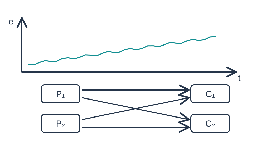
Label the events that may trigger drift
Record startup, direction reversal, refill, reservoir-level change, priming, stop and restart. Align fluid temperature, temperature near the pump and inlet/outlet pressure with each dispense. Similar trend shapes can have different causes; event labels select the next controlled test.
A reversal-specific first-dispense error suggests backlash, valve delay or pressure establishment. A level-dependent trend suggests static head or reservoir venting. Brief recovery after priming followed by recurrence supports ongoing gas ingress or release, but its source still needs confirmation.
Test reversible conditions first
Keep program, backpressure and temperature consistent while separately testing controlled priming, fixed reservoir level, reservoir venting and a permitted lower aspiration speed. Change one variable at a time and return to the baseline to distinguish cause from a time effect.
Do not replace the pump, fluid and tubing together. A reference circuit should preserve the necessary valve sequence and equivalent outlet loading. Otherwise recovery merely proves that the overall conditions changed.
Cross-swap pumps and circuits
Test the suspect and reference pumps in the same qualified reference circuit, then test both in the complete instrument circuit: a 2×2 comparison. Match target volume, fluid temperature, level, drive and valve sequence, and confirm that the reference pump is itself qualified.
If the problem follows one pump, isolate its valve, seal and motion components next. If both pumps drift only in the instrument circuit, investigate the system first. An interaction can involve load or driver matching; it need not fit a simple pump-versus-circuit diagnosis.
| Combination | Reference circuit | Instrument circuit |
|---|---|---|
| Reference pump | Confirm qualified baseline | Does the system trigger drift? |
| Suspect pump | Does the problem follow the pump? | Reproduce the original symptom |
| Common controls | Same fluid, temperature, program | Equivalent outlet load; record inlet pressure |
Understand the limits of pressure-hold evidence
Where permitted by the design and pressure rating, compare holds at the same initial pressure, valve state and temperature against a historical or new-part baseline. Faster decay supports leakage or changing stored volume, but cannot identify a specific failed valve seat by itself.
Gas, tubing relaxation, temperature and sensor location also affect the trace. Backlash usually relates to reversal and should be tested separately. Increasing compensation repeatedly can hide temperature, leakage or gas problems without resolving them.
Require converging evidence before diagnosing wear
After excluding measurement, priming, level and control differences, stronger wear evidence is repeatable degradation that follows an aged component, recovery after replacing that component, and inspection consistent with the observed failure. Record contamination, crystallization and material changes separately.
Maintain new-unit, life-stage and post-maintenance baselines. Requalify at the original trigger duration and adverse fluid/temperature conditions. EA, EAS, SM or TM full-stroke figures do not establish drift limits for every volume and reagent; instrument requirements and measurement uncertainty define acceptance.
Related reading and specifications
Technical references
Frequently asked questions
Does progressively lower delivery prove valve leakage?
No. Level, venting, gas, temperature and measurement error can produce similar trends. Use controlled comparisons and pressure-hold evidence.
Does a passing CV rule out drift?
No. Short-window scatter can remain small while the mean moves. Review mean bias and the time-ordered data.
Does recovery after priming rule out wear?
It supports gas involvement but does not exclude other mechanisms. Continue operation, observe recurrence and compare components.
How do I distinguish pump and instrument causes?
Cross the suspect/reference pumps with reference/instrument circuits, holding fluid, program and equivalent load constant, then isolate individual components.