
Does a Miniature Diaphragm Pump Need a Pulsation Damper? Validate It with an A/B Test
A damper is justified by load performance and its trade-offs in startup, trailing liquid, cleaning and dead volume. Define acceptable ripple at the load, then compare steady operation and start-stop delivery with and without damping under the same task. A smoother trace alone is not a passing result.
Turn smoother flow into a load acceptance requirement
Reciprocating delivery creates periodic flow; tubing resistance, inertia and compliance shape pressure at the load. The general pulsation guide covers those causes. This article addresses the narrower decision: whether an added damper is worth keeping and how to qualify it.
Specify measurement location, sensor bandwidth, allowed peak-to-peak ripple or another defined metric, and the final function: flow-cell signal, spray uniformity or nuisance protection trips. If the task only requires reliable bulk transfer and already passes, an accessory may offer little benefit.
Stored liquid changes startup and stopping
A damping element stores some liquid during higher pressure and releases it as pressure falls. Effective compliance can be understood as volume change per pressure change, but depends on pressure and construction. A 300 or 600 mL/min rating cannot determine a universal chamber volume.
More storage can lengthen pressure buildup and produce liquid after stopping. Assess compatibility, cleanability, trapped gas, pressure rating and orientation. Deliberately leaving bubbles in the process fluid is not equivalent to using a qualified, separated damping element.
Ppp = Pmax − Pmin; Ceff ≈ ΔV / ΔPCompare Ppp at the same location and bandwidth. Ceff represents effective compliance over a selected pressure interval, not a universal sizing rule or guaranteed attenuation.Compare the same task and disclose operating-point changes
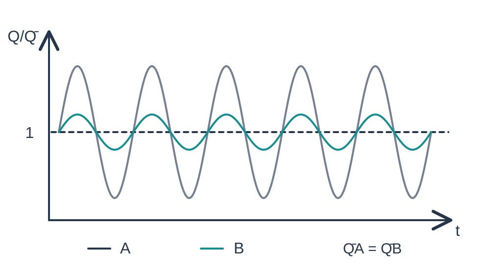
A is the original circuit; B adds the damper. Keep pump, fluid temperature, reservoir level, main geometry, end load and measurement locations consistent. Record the complete model, drive command and control version. Install and set the damper according to its manufacturer's requirements.
First compare identical drive commands to expose changes in mean flow and pressure. If the specific pump supports speed control, add a comparison at matched average flow and disclose the changed drive. A smoother trace at lower flow is not a matched-operating-point damping result.
Measure steady flow and short cycles separately
At steady state, record load pressure peaks and troughs, average flow and the process signal with the same bandwidth. Relative pressure ripple is useful only with a meaningful nonzero mean and a consistent pressure reference; near zero mean, report absolute peak-to-peak values.
Run the actual start-stop sequence and measure time to functional pressure, delivered volume, trailing liquid and the next cycle's initial state. Match totalizer and collection windows. Liquid retained in the damper is not automatically a leak.
Keep or remove the damper using the complete result
Keep B only when ripple and load function improve while task volume, startup, trailing liquid and cleaning also pass. If steady performance improves but short-cycle delivery or post-stop dripping fails, revise the geometry, installation or control and repeat the test.
If A already meets the function and B only steadies the display while adding retained liquid and maintenance, retaining A may be appropriate. If neither passes, reconsider inlet supply, resistance or pump architecture instead of treating a damper as a universal remedy.
| Acceptance item | Measure in A and B | Condition for retaining B |
|---|---|---|
| Steady function | Load pressure and process signal | Meets predefined functional limits |
| Transfer task | Same-window flow and delivered volume | Task passes; differences are explained |
| Start and stop | Pressure rise time, tail, next-cycle state | Within project limits |
| Maintenance and compatibility | Retained liquid, cleaning, gas, materials | Added burden is acceptable |
What DPL30 and DPL60 specifications establish
Official specifications list DPL30 at 300 mL/min no-load flow, 100 kPa rated pressure and 6 mH₂O self-priming height; DPL60 at 600 mL/min, 100 kPa and 3 mH₂O respectively. These are separate performance items, not a simultaneous operating-point guarantee or a pulsation percentage.
Use speed control only on a specific five-wire or other configuration whose interface explicitly supports it. Brushless does not universally mean PWM-controllable. Retain model, drive, sensor location, fluid temperature, filter state and load conditions with the A/B results.
Related reading and specifications
Technical references
Frequently asked questions
Does every miniature diaphragm pump need a damper?
No. Establish whether real pulsation affects the load, then weigh the benefit against dead volume, cleaning, startup and trailing liquid.
Is a larger damper always better?
No. Volume, pressure response, frequency and fluid all matter. More storage may increase delay and trailing liquid.
Can software filtering replace hydraulic damping?
Filtering changes a signal or display; it does not reduce physical pressure variations acting on valves, nozzles or flow cells.
How should a lower flow after damping be compared?
Report the identical-drive result first. If speed control is supported, also compare matched mean flow while disclosing the new drive and operating point.