
Diaphragm Pump Bubbles and Noise: Cavitation, Air Ingress or Outgassing?
Bubbles, noise and reduced flow do not individually prove cavitation. Separate incoming air, dissolved-gas release and local vapor formation using synchronized absolute inlet pressure, fluid temperature, bubble location and flow. A normal average inlet pressure cannot exclude a brief low-pressure region inside the pump; build evidence through controlled comparisons.
Use absolute pressure for the vapor boundary
Cavitation involves vapor formation at local low pressure and subsequent collapse when pressure recovers. External air ingress and dissolved-gas release are different sources, require different remedies and can coexist with vapor formation.
Add local atmospheric pressure to gauge pressure before comparing with the actual fluid's vapor pressure at its temperature. Losses and transients remain between the inlet sensor and chamber. An inlet average above vapor pressure is therefore not proof of cavitation-free operation.
Pabs = Pgauge + Patm; Plocal,min,abs > Pvapor(T) + marginThe second relation is a design target, not a safety conclusion from an inlet sensor alone. Vapor pressure must match fluid and temperature; validate the required margin for the actual system.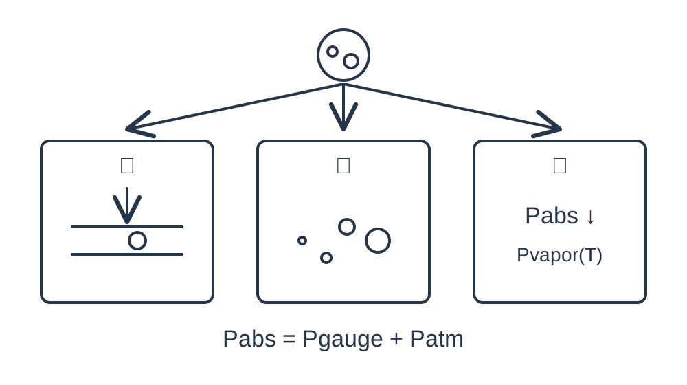
What evidence distinguishes the three mechanisms?
Record where bubbles first appear, suction-stage pressure and fluid temperature. A connection may admit air under vacuum without leaking liquid outward. Improvement after degassing supports dissolved-gas involvement but does not independently exclude vapor formation.
Vapor bubbles can form and collapse inside the pump before they become visible downstream. Noise, reduced flow response to speed and pressure fluctuations are clues, not isolated proof. Interpret them together with the response to improved inlet conditions.
| Mechanism | Gas source | Priority comparison |
|---|---|---|
| Air ingress | External air | Suction sealing and sectional swaps |
| Outgassing | Dissolved gas | Same-fluid, same-temperature degassing |
| Vapor formation/cavitation | Liquid vapor | Inlet losses, absolute pressure, temperature |
| Coexisting mechanisms | Combined sources | Stepwise changes and baseline repeats |
Inspect inlet restrictions and reservoir conditions
Check suction height, minimum level, reservoir venting, filter loading, flattened tubing and the smallest fitting bore. Increasing the main tube diameter may not fix a valve or filter restriction. Use sectional pressure readings or permitted substitution tests.
Higher temperature can reduce viscosity while increasing vapor pressure and encouraging outgassing. Easier flow does not necessarily mean a larger safety margin. Hot or volatile formulations require properties for the actual composition and temperature.
Run three controlled comparisons
First retain the liquid and shorten the inlet or replace a confirmed restrictive component. Second check seals and improve reservoir static head within permitted limits. Third compare the same fluid before and after degassing at equal temperature. Return to baseline and record minimum inlet pressure, flow, noise and bubbles.
A separate lower-speed test is useful only when the specific configuration supports controlled speed. Do not apply incompatible PWM to two-wire or unverified versions. Improvement from reduced inlet demand supports several mechanisms and cannot alone confirm cavitation.
State the sensor and inference limits
Synchronize inlet absolute pressure, outlet pressure, flow and temperature. Record sensor response, sampling, mounting cavities and distance to the pump. A slow instrument can hide troughs; its installation can introduce gas pockets or additional resistance.
Set pressure margin using manufacturer information, local dynamic assessment and testing. No universal kPa threshold or unmeasured NPSH requirement is supplied here. Where the critical region cannot be measured, report supported hypotheses or reduced risk rather than direct proof of the mechanism.
Self-priming height is not a cavitation guarantee
The official DPL30 self-priming height is 6 mH₂O and DPL60 is 3 mH₂O. These water-based figures do not guarantee safe operation for every reagent at a 6 m or 3 m installation height. DPL30H's 600 kPa rated outlet pressure likewise does not establish inlet vapor margin.
Requalify at maximum fluid temperature, minimum reservoir level, representative end-of-life filter loading, maximum task flow and start-stop/restart conditions. Preserve mean delivery and dynamic signals, and respect material/fluid limits. Recovery with room-temperature water does not close a real-reagent issue.
Related reading and specifications
Technical references
Frequently asked questions
Do bubbles or noise prove cavitation?
No. Air ingress, outgassing, residual gas and other faults can look similar. Combine pressure evidence with controlled comparisons.
Can −50 kPa gauge be compared directly with vapor pressure?
No. Convert using local atmospheric pressure and account for actual fluid, temperature, sensor location and transient losses.
Does quieter operation at lower speed confirm cavitation?
It only supports speed-dependent inlet or system effects. Air ingress, outgassing, resonance and supply limitations can also change with speed.
Does DPL30's 6 m self-priming rating ensure no cavitation at 6 m?
No. Priming test conditions differ from continuous service. Fluid, temperature, tubing losses, level and pulsation change the risk.