
Which Has a Greater Effect on a Miniature Diaphragm Pump: Suction-Line or Discharge-Line Resistance?
Pressure loss on either the suction or discharge side increases the differential pressure carried by a miniature diaphragm pump, but there is no universal rule that one side is always more important. The suction side more readily affects initial priming, chamber filling, sensitivity to air leakage, outgassing, and cavitation. The discharge side more often appears as increased backpressure, reduced flow, and deadheading. Diagnose the system by observing inlet absolute pressure, outlet pressure, and flow on the same time axis.
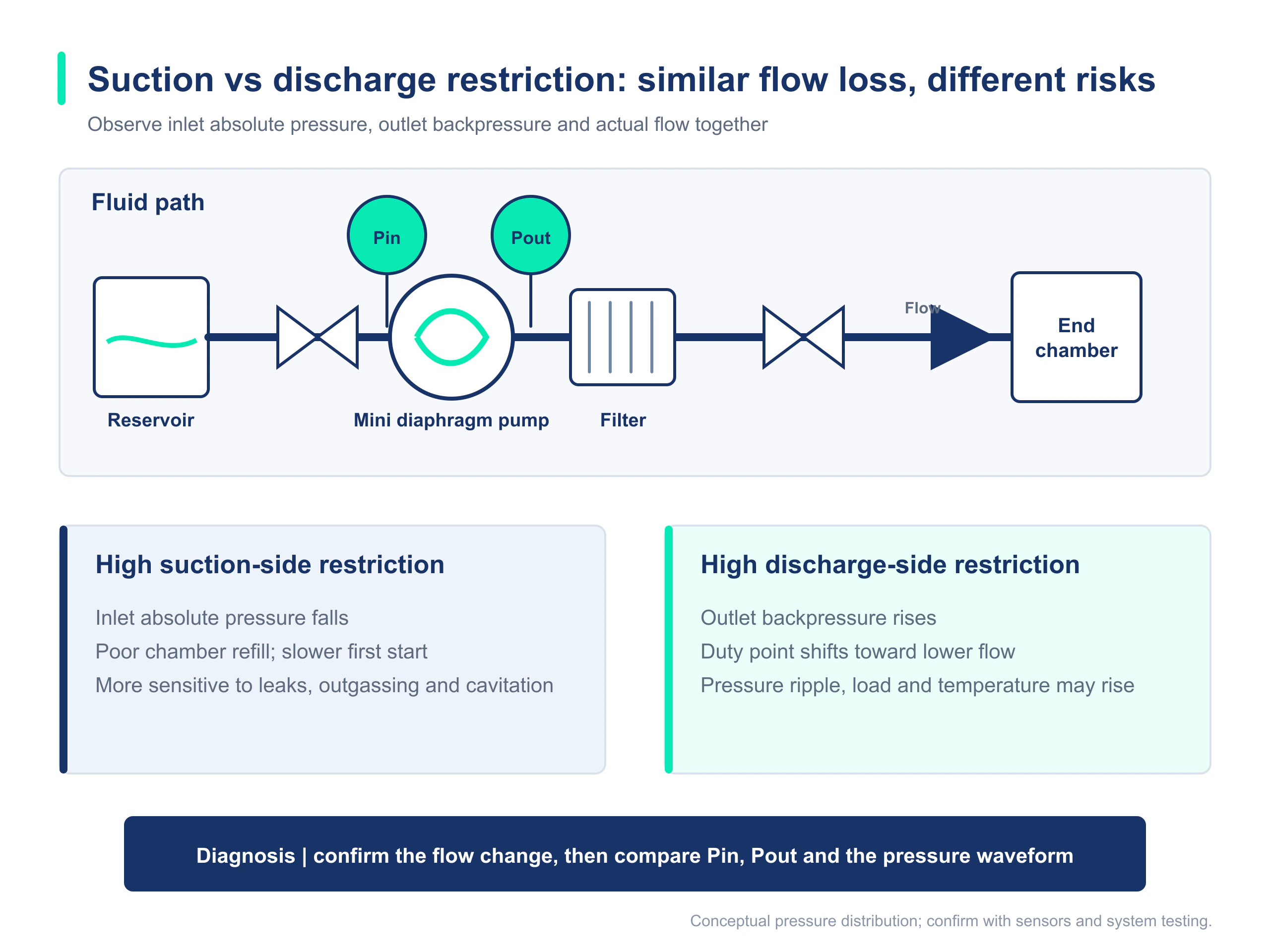
1. Put resistance on both sides into the same pressure relationship
ΔPpump = Pout - PinPin and Pout must use the same pressure reference. Gauge or absolute pressure can be used consistently for pump differential pressure; cavitation analysis requires inlet absolute pressure separately.In an approximate comparison with all other conditions unchanged, an additional 20 kPa loss upstream of the pump or an additional 20 kPa backpressure downstream can both move the operating point toward lower flow. Suction-side loss also lowers local absolute pressure at the pump inlet and inside the chamber, amplifying the effects of small air leaks, falling liquid level, and gas release. Failure severity therefore cannot be judged from total differential pressure alone.
| Comparison | Increasing suction-side resistance | Increasing discharge-side resistance |
|---|---|---|
| Direct pressure change | Inlet absolute pressure falls and the magnitude of negative gauge pressure increases | Outlet gauge or absolute pressure rises |
| Typical startup behavior | Initial priming slows and a stable liquid column may be difficult to establish | Priming usually remains possible, but discharge slows |
| Typical operating behavior | Bubbles, flow fluctuation, noise, and deterioration as liquid level falls | Higher outlet pressure, lower flow, and deadheading under blockage |
| Primary additional risks | Sensitivity to air leaks, incomplete chamber filling, outgassing, or cavitation | Motor and structural load, temperature rise, and pressure ratings of filters or tubing |
| Key measurement | Absolute pressure and waveform close to the pump inlet | Backpressure and waveform close to the pump outlet |
2. Why excessive suction-side resistance more readily causes failure to prime
Longer or smaller-ID suction tubing, more bends, and higher losses across an inlet valve, filter, or fitting generally reduce pump-inlet absolute pressure. A falling reservoir level or increased suction lift adds a static-pressure effect. During initial startup, the line contains air and the pump chamber must first vent and establish a liquid column, so the problem is often more pronounced than during stable operation.
- Initial priming time becomes much longer and temporarily recovers after pre-filling or reducing suction lift.
- A small air leak exists at an inlet fitting. No liquid may leak outward, but the pump cannot establish a stable liquid column.
- Flow falls as reservoir level drops, or operation becomes less stable with hot or volatile fluids.
- Bubbles are visible in a transparent tube section, pressure and flow pulsation intensify, and abnormal noise appears.
Pin,abs = Patm + Pin,gaugeThis conversion applies when a gauge-pressure sensor uses local atmospheric pressure as zero. Negative gauge pressure makes inlet absolute pressure lower than local atmospheric pressure. Use the actual pressure reference for a sealed pressurized source or different reference conditions.Plocal,abs > Pvapor(T) + engineering marginThis expresses a necessary engineering constraint to prevent vaporization in local low-pressure regions. Pvapor must correspond to the actual fluid and temperature. Determine the required margin from pressure pulsation, measurement location, line losses, and validation results.3. Why excessive discharge-side resistance looks more like pressure without enough flow
Small tubing, valves, filters, needles, nozzles, and pressurized chambers on the discharge side raise outlet backpressure. As backpressure rises, a miniature diaphragm pump generally moves along its flow-pressure curve to a lower-flow operating point. Operating current, temperature rise, pressure pulsation, and structural load may also change.
| Field symptom | Evidence supporting excessive discharge resistance | Also rule out |
|---|---|---|
| The pump primes normally but discharges slowly | Inlet pressure remains near baseline while outlet backpressure rises significantly | Fluid viscosity, pump-terminal voltage, and flowmeter error |
| Flow falls after the filter has been used for some time | Differential pressure across the filter increases over time | Suction loss caused by an inlet filter |
| Flow changes suddenly after a valve switches | Outlet pressure changes at the same time in the corresponding valve position | Valve direction, incomplete opening, or control timing |
| The system deadheads or protection trips when the outlet is blocked | Outlet pressure rises rapidly while flow approaches zero | Rated pressure of the full fluid path and safe pressure-relief measures |
Rated pressure is not permission for continuous deadheading and does not replace system pressure qualification. Check hoses, fittings, valves, filters, sensors, and chambers against their own controlled ratings. Product and equipment engineering must jointly confirm protection logic and allowable duration under blockage.
4. Combine pressure evidence and symptoms to distinguish failures on the two sides
| Symptom | Inlet-pressure signature | Outlet-pressure signature | Check first |
|---|---|---|---|
| Slow initial priming or failure to prime | Low or abnormal fluctuating inlet absolute pressure | May not rise significantly | Suction tubing, liquid level, fitting air leaks, inlet valve, and inlet filter |
| The pump has primed but flow is low | Near baseline | Backpressure above baseline | Discharge tubing, filter, valve, needle, and downstream chamber |
| Flow fluctuates with visible bubbles | Abnormal absolute pressure or waveform | May fluctuate at the same time | Outgassing, inlet air leakage, local vaporization, valve elements, and tubing deformation |
| Backflow or siphoning after shutdown | Affected by liquid-level static pressure and sealing | Abnormal residual-pressure release | Check valve, installation height, siphon path, and leakage risk |
| Both pressures deviate from baseline | Inlet absolute pressure falls | Outlet backpressure rises | Added resistance exists on both sides; bypass each section separately |
Place sensors as close as practical to the pump inlet and outlet, and record them in sync with flow, liquid level, valve position, pump-terminal voltage, and time. A single remote downstream pressure measurement omits frictional and local losses between the sensor and pump. A stabilized average alone can miss startup and valve-switching transients.
5. Should the filter be upstream or downstream of the pump? Decide from purpose and boundaries
Filter location cannot be reduced to 'always put high-resistance components on the discharge side.' First define the filtration purpose, where particles originate, the pump's particle tolerance, the filter medium's allowable positive and negative pressure, worst-case differential pressure after clogging, and whether the system must protect the pump or the downstream components.
| Arrangement | Potential purpose | Boundary that must be validated |
|---|---|---|
| Inlet filtration | Prevent upstream particles from entering the pump and protect valve elements and the pump chamber | Inlet absolute pressure after loading, initial priming, self-priming time, air-leak risk, and filter-medium collapse resistance |
| Outlet filtration | Protect downstream components or provide fine filtration after the pump | Added backpressure, maximum differential pressure under blockage, filter-housing pressure rating, pump operating point, and overpressure protection |
| Coarse inlet filter plus fine outlet filter | Address both upstream particle risk and downstream cleanliness requirements | Combined end-of-life differential pressure and maintenance strategy for both filters |
| No general-purpose filter | The fluid is clean and the system uses other contamination controls | Particle tolerance of the pump and downstream components must be confirmed by controlled documentation |
6. Practical sequence for fluid-path layout and validation
- Draw the complete path from the liquid source to the endpoint, marking elevation differences, tube IDs and lengths, valves, fittings, filters, and minimum bores.
- Place the pump as close to the liquid source as practical to reduce unnecessary suction lift. Keep inlet tubing short, adequately sized, minimally bent, and reliably sealed.
- Place pressure measurement points near the pump inlet and outlet. Record absolute pressure on the inlet side or retain a pressure reference that supports reliable conversion.
- Establish a low-resistance baseline first, then add suction-side and discharge-side components separately and use sectional bypasses to confirm their pressure drops.
- Retest worst-case conditions at minimum liquid level, real fluid temperature, end-of-life filter loading, valve switching, and final installation orientation.
- Record flow, pressure waveform, pump-terminal voltage, current, priming time, bubbles, noise, and temperature rise together to create a traceable acceptance record.
For more on operating points and pressure curves, seeHow to Read a Diaphragm Pump Flow-Pressure Curve.
For 300 mL/min-class liquid circuits, review the DPL30 liquid diaphragm pump series.
For higher-flow liquid circuits, review the DPL60 liquid diaphragm pump series.
When discharge resistance creates a high-backpressure operating point, review the DPL30H high-pressure liquid diaphragm pump series.
7. Which conclusions still require product testing or engineering confirmation
| Item to confirm | Why this article alone cannot determine it | Recommended evidence |
|---|---|---|
| Allowable inlet absolute pressure and self-priming boundary | Affected by model, speed, fluid, temperature, tubing, and valve-element condition | Controlled specification for the model and startup testing in the real fluid path |
| Safety margin against cavitation or outgassing | One inlet measurement point cannot fully represent the minimum instantaneous pump-chamber pressure | Pressure waveform, fluid vapor pressure, transparent-tube observation, and durability validation |
| Maximum continuous outlet backpressure | Rated pressure, maximum pressure, and short-duration stall limits are different concepts | Product specification plus temperature-rise, current, life, and protection-strategy testing |
| Filter installation location | Depends on filtration purpose, particle risk, pump tolerance, and filter pressure capability | Risk analysis and full-system testing through end-of-life loading |
| Failure acceptance criteria | Equipment requirements for priming time, flow fluctuation, noise, and dosing error differ | Equipment requirements, inspection standards, and prototype statistical data |
This article provides a method for distinguishing failure modes, not guaranteed values for a specific pump. Inlet pressure, backpressure, filter location, and allowable continuous conditions must be checked against the controlled documentation for the model and validated with the final fluid and complete fluid path.
FAQ: Common Questions About Suction Resistance and Discharge Backpressure
Do an additional 10 kPa loss on the suction side and 10 kPa on the discharge side have exactly the same effect?
Their contribution to total pump differential pressure may be similar, but the failure modes differ. Suction-side loss also lowers inlet absolute pressure and raises the risks of incomplete chamber filling, sensitivity to air leakage, outgassing, and cavitation. Discharge-side loss more directly appears as higher backpressure and lower flow.
Should a filter be installed before or after the pump?
It depends on filtration purpose, particle source, pump particle tolerance, and allowable filter differential pressure. Inlet filtration requires validation of loaded inlet absolute pressure and initial priming; outlet filtration requires validation of loaded backpressure, filter-housing pressure capability, and overpressure protection. There is no universal answer.
The pump makes noise but no liquid comes out. Which side should I check first?
First check the liquid source, liquid level, inlet tubing, fitting air leaks, valve orientation, and initial priming. Then check for an outlet blockage or excessive backpressure. The fastest distinction is to measure pressure near both the pump inlet and outlet while observing bubbles in a transparent tube section.
Can cavitation be assessed from negative inlet gauge pressure alone?
No. Convert inlet pressure to absolute pressure and compare it with the fluid saturation vapor pressure at the actual temperature. Also consider local instantaneous low pressure in the pump chamber, pressure pulsation, and losses between the measurement point and chamber. Confirm with testing using the real fluid.
Is placing the pump below the liquid level always better?
Positive static pressure at the inlet generally helps chamber filling, but it is not unconditionally better. Evaluate siphoning, backflow after shutdown, leakage, source-pressure variation, and equipment safety boundaries, and confirm the allowable inlet pressure of the pump and upstream components.
Can the fluid-path problem be diagnosed by measuring only outlet pressure?
No. Outlet pressure does not reveal suction loss, air leakage, or insufficient inlet absolute pressure. At minimum, measure inlet pressure, outlet pressure, and flow together, and record liquid level, valve position, fluid temperature, and pump-terminal power.