
Why Does Actual Flow Change So Much When the Tubing Size Changes on the Same Miniature Diaphragm Pump?
Even when the pump is unchanged, installed flow can change because of tubing inner diameter, length, bends, and the minimum bore of fittings. When flow falls after a tubing change, the effective response is neither to blame the pump first nor to enlarge every tube indiscriminately. Measure inlet pressure, outlet pressure, and accumulated flow together to determine where the added restriction actually occurs.
Tubing outer diameter mainly determines interface fit; the fluid passes through the inner bore. Tubes with the same OD can have different IDs because of wall-thickness differences. Bends, overtightened cable ties, or excessive fitting insertion can also create a local effective passage smaller than the nominal ID. The real engineering task is to inventory the minimum effective bore and pressure loss of every section, not a single size printed on the package.
1. Turn 'flow dropped after changing the tubing' into comparable data
Flow before and after a tubing change is comparable only when the test boundaries are consistent. Any change in pump-terminal voltage, fluid, fluid temperature, reservoir level, downstream termination, run time, or flow-calculation method can compound the tubing change. Keep the old tubing as a baseline and perform an A/B test on the same pump.
| Item to hold constant or record | Recommended record | Misdiagnosis to avoid |
|---|---|---|
| Pump and drive | Use the same pump; record loaded terminal voltage, current, and PWM parameters | Mistaking supply-voltage drop or speed-control changes for a tubing-size effect |
| Fluid and temperature | Use the same fluid batch; record fluid temperature, viscosity, or formulation state | Mistaking a viscosity change for a tubing difference |
| Fluid-path boundaries | Fix the liquid level, downstream height, valve positions, filter, and needle | Changing several restrictions at once and losing the ability to locate the cause |
| Tubing condition | Record material, measured ID, length, lot, bend radius, and fixing method | Comparing only OD or product name |
| Flow measurement | Use the same accumulation time and cross-check with gravimetric measurement when needed | Comparing non-equivalent instantaneous readings from pulsating flow |
2. Use inlet pressure, outlet pressure, and flow to identify which side contains the restriction
Place pressure measurement points as close as practical to the pump inlet and outlet. Use the same pressure reference before and after the tubing change, and record stabilized average flow at the same time. A flow drop alone confirms only that the operating point has changed. Recording both pressures makes it much easier to determine whether the change comes from the suction section, the discharge section, or something outside the fluid path.
ΔPpump = Pout - PinPin and Pout must use the same pressure reference. Gauge or absolute pressure can be used consistently to compare pump differential pressure; cavitation analysis requires absolute pressure.| Main symptom after the tubing change | Pressure evidence | Check first |
|---|---|---|
| Priming slows and flow drops | Inlet pressure falls relative to baseline while outlet pressure does not rise significantly | Suction tubing that is too small or long, flattened bends, a restricted inlet fitting, or an air leak |
| The pump primes, but discharge flow drops | Inlet remains near baseline while outlet backpressure rises | Discharge tubing, outlet fitting, filter, valve, needle, or downstream chamber |
| Inlet pressure is lower and outlet pressure is higher | Differential pressure across the pump increases at both ends | Added restriction on both suction and discharge sides, or a complete tubing-set change |
| Pressure stays near baseline but flow remains low | Average static pressure at both ends changes little | Inlet air leakage, bubbles, valve dynamics, pump-terminal voltage, fluid properties, or measurement response |
| Flow repeatedly rises and falls | The pressure waveform fluctuates at the same time | Intermittently flattened tubing, bubbles, fitting air leaks, valve orientation, or pulsating-flow measurement issues |
Average pressure can hide the transient pulsation of a diaphragm pump. If the problem appears only during startup, valve switching, or high-flow operation, observe the pressure waveform, bubbles in a transparent tube section, and tubing deformation rather than copying only one stabilized display value.
3. Why a small ID change can cause a large pressure-drop change
When the assumptions of a circular constant-ID straight tube, Newtonian fluid, and fully developed laminar flow are valid, the Hagen-Poiseuille relation can be used to estimate how sensitive straight-tube pressure drop is to inner diameter:
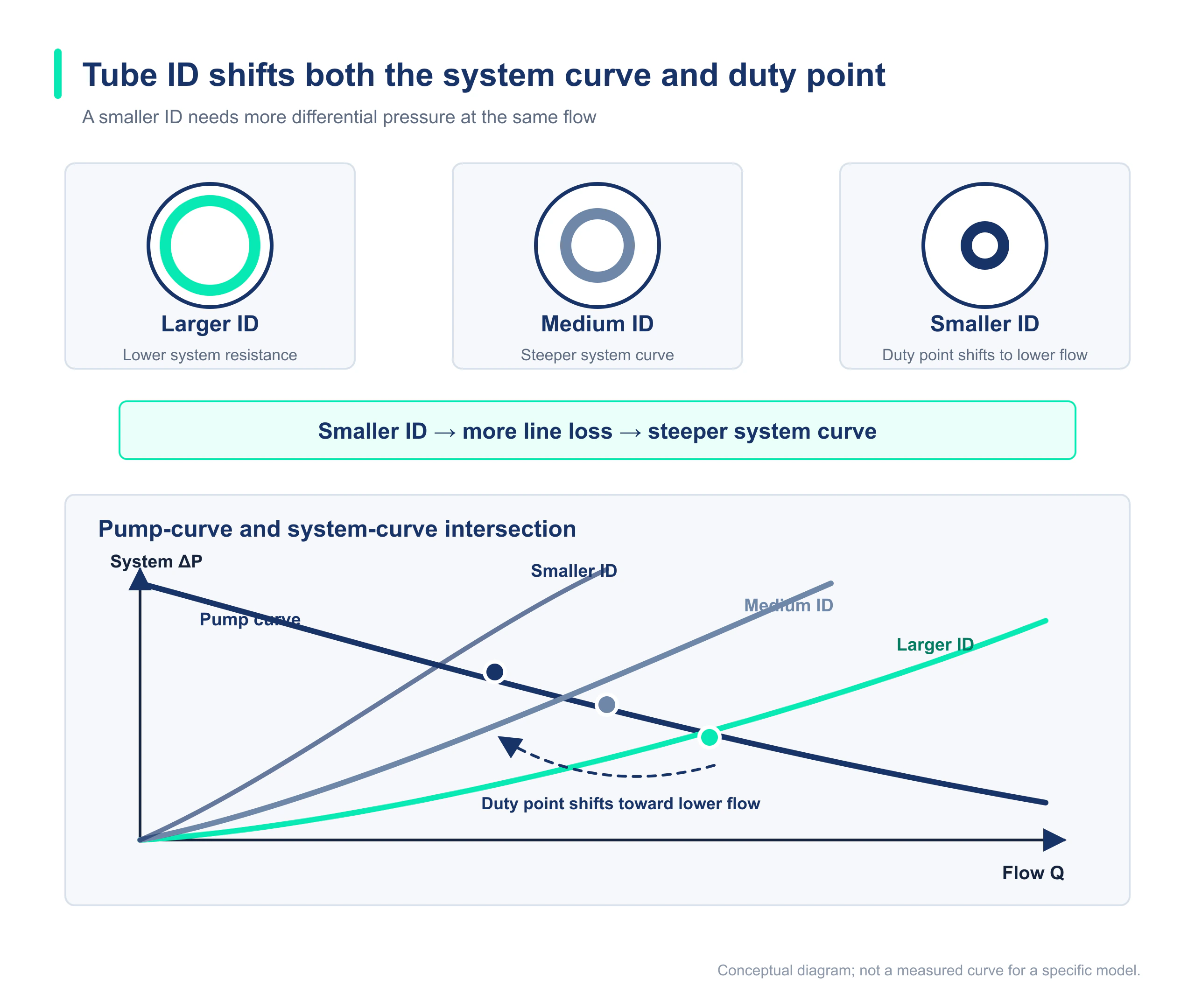
ΔP = 128μLQ / (πd⁴)μ is dynamic viscosity, L is tube length, Q is volumetric flow, and d is tube inner diameter. The equation excludes entrance effects, fittings, valves, filters, tubing deformation, and diaphragm-pump pulsation. It is only a preliminary screening tool when its assumptions apply.In a theoretical comparison at the same flow, length, and viscosity, reducing ID from 3.2 mm to 2.0 mm increases the straight-tube pressure-drop ratio to about 6.55; reducing it to 1.6 mm increases the ratio to about 16. This shows why ID deserves early attention, but it does not mean actual flow will fall by a factor of 6.55 or 16. Actual flow settles at the new intersection of the system curve and pump curve.
For the complete relationship among pump curves, system curves, and operating points, readHow to Read a Diaphragm Pump Flow-Pressure Curve.
For preliminary fluid-path estimates, use theFluid Resistance Calculator; final decisions still require testing with the real fluid path.
4. Do not inspect only the tubing: the minimum bore may be hidden inside a fitting or component
| Potential restriction | On-site inspection method | Evidence |
|---|---|---|
| Tubing itself | Measure actual ID, total length, and the cross-section after bending | Whether pressure and flow recover with a short straight tube |
| Barbed fitting or adapter | Check the internal minimum bore, steps, and insertion depth | Whether pressure drop falls after bypassing or replacing the fitting |
| Valve and filter | Test the baseline, the newly installed component, and its loaded state separately | Whether differential pressure across the component becomes a dominant pressure term |
| Needle, nozzle, or capillary | Check ID, length, and entrance geometry | Even a short component can dominate total fluid-path resistance |
| Tubing fixing point | Inspect cable ties, clips, tight bends, and heat-softened sections | Whether local flattening or periodic closure occurs during operation |
A tubing connection size in product documentation primarily describes interface compatibility. It does not mean every length, material, and routing method will maintain the same flow. If a filter, valve, or needle already accounts for most of the pressure drop, enlarging ordinary straight tubing may deliver little benefit.
5. Recommended segmented-replacement diagnostic procedure
- With the old tubing configuration, record inlet pressure, outlet pressure, pump-terminal voltage, current, accumulated flow, and priming time to establish a repeatable baseline.
- Replace tubing on only one side while keeping the other side and downstream components unchanged. Test the suction side first, then the discharge side.
- Use a short straight tube to test the tubing itself, then progressively add bends, fittings, valves, and the filter following the actual routing.
- Each time a component is added, record the pressure change across it and the corresponding flow change to identify the step with the largest pressure-drop increase.
- If a fitting or local restriction is suspected, replace it with a bypass component of known bore. Do not judge from appearance.
- Retest in the final installation orientation with the real liquid level, fluid, and complete control program, and retain the tubing lot, photographs, and data version.
6. When the problem still cannot be attributed to tube ID
If the A/B test cannot reproduce the issue, or the two pressures do not change consistently with the tubing, expand the diagnostic scope. Inlet air leakage, residual air, fluid viscosity and temperature, valve orientation, filter condition, pump-terminal power, sample wear, and a flowmeter's response to pulsating flow can all produce similar symptoms.
| Further check | Recommended evidence | Boundary requiring engineering confirmation |
|---|---|---|
| Whether the pump is normal | Retest with the specified fluid in a low-resistance baseline loop | Acceptance limits should come from the controlled specification or inspection standard for the model |
| Whether the new tubing is conforming | Measure ID, wall thickness, hardness, lot, and deformation under suction | Dimensional and material tolerances require confirmation by supply-chain and R&D teams |
| Whether the operating point meets equipment needs | Continuously record flow, pressure, temperature rise, and startup under real conditions | Acceptance criteria should be defined by cycle time, dosing accuracy, and life targets |
| Whether long-term operation is stable | Retest at end-of-life filter loading, minimum liquid level, and temperature limits | A short water test cannot replace life validation with the real fluid |
FAQ: Common Questions About Flow Changes After Replacing Tubing
Why can tubes with the same outer diameter produce different flow after replacement?
Wall-thickness tolerance changes inner diameter, while material hardness, bend condition, and deformation under suction change the effective bore. Record actual ID, length, bend radius, and lot instead of comparing only OD.
Will replacing every tube with a larger ID always increase flow?
No. If a needle, filter, valve, fitting minimum bore, or downstream chamber dominates system resistance, enlarging ordinary straight tubing may have little effect. Use segmented differential-pressure measurements to find the primary restriction first.
Will the pump automatically rise to its rated pressure when tube ID decreases?
That cannot be assumed. Changing the tubing shifts the system curve, and the pump operates at the intersection of its performance curve and the new system curve. The new pressure and flow depend on the complete fluid path, drive, and pump curve. Rated pressure is not an operating point that is reached automatically.
Can one short, sudden reduction in bore still have a noticeable effect on flow?
Yes. In addition to friction in the small-bore section, a short restriction produces local contraction and expansion losses. If its bore is much smaller than the rest of the path, it can still become the main restriction. Confirm with a bypass or replacement component.
What is the fastest way to tell whether the new tubing or the pump is the problem?
Perform a repeatable A/B test between the old and new tubing on the same pump while recording inlet pressure, outlet pressure, pump-terminal voltage, and accumulated flow. Only when reinstalling the old tubing restores performance and the new tubing repeatedly triggers the abnormal result does the evidence support locating the problem in the new tube or its assembly.