
What Is a Programmable Syringe Pump? Operation, Fluid Routing and Automation
A programmable syringe pump uses a motor to control syringe plunger displacement and speed, executing aspiration, dispensing, pauses and repeated actions through commands. With a routing valve, it can connect reagent reservoirs, reaction vessels and wash paths into an automated dispensing process. Instrument development therefore needs to define volume, fluid connections and timing together.
This article covers OEM syringe pumps for analytical instruments and automation, focusing on metering through fixed, liquid-filled tubing. The module works with reservoirs, tubing, dispensing needles, vessel positioning and control software to complete the instrument's task.
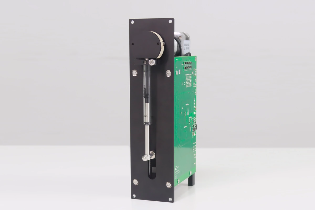
01What do the syringe, drive and valve do?
The drive converts motor rotation into linear plunger movement. Retracting the plunger increases the syringe chamber volume and draws liquid through the connected inlet. Advancing it reduces the volume and expels liquid through the outlet. The valve chooses the source and destination; the syringe meters the liquid. Their timing must be coordinated.
For an ideally filled, leak-free fluid path, geometric displacement is V = A × Δx and nominal flow is Q = A × v, where A is the syringe's internal cross-sectional area, Δx is plunger travel and v is plunger speed. Bubbles, seals, tubing compliance and liquid remaining at the outlet can alter delivered volume. Completing the commanded stroke does not prove that all the liquid reached the receiving vessel.
This differs from an air-displacement pipetting module, which moves liquid in a disposable tip through an air cushion. In the fixed fluid paths discussed here, reagent generally contacts the syringe, valve and tubing, making chemical compatibility and cleaning paths part of the design.
02How does a complete dispensing cycle work?
Consider a fixed dose transferred from a reagent reservoir to a reaction vessel. The program manages a complete cycle. Prime and remove air at startup, after changing a reservoir or whenever air enters the path. During routine batches, schedule refills according to the remaining volume and the cleaning strategy.
- Prime: connect the source and cycle liquid to waste along the intended path to remove air from the syringe and relevant tubing.
- Aspirate: connect the required source and draw the required amount at the selected stroke and speed, allowing pressure to settle where necessary.
- Switch: stop metering motion, select the destination outlet and confirm the path and vessel position.
- Dispense: deliver the selected volume at the selected speed. For repeated doses from one aspiration, track the remaining usable volume.
- Refill: return to the source when capacity is insufficient and include this interruption in batch timing.
- Clean: at a source change or method-defined point, flush shared segments with a compatible wash liquid and route it to waste.
Normally, stop plunger movement before switching the valve and establish the destination path before restarting aspiration or dispensing. If valve-position feedback is unavailable, provide appropriate delays and fault handling and verify switching time. Never drive the plunger with all relevant paths closed. A command being sent does not confirm completion.
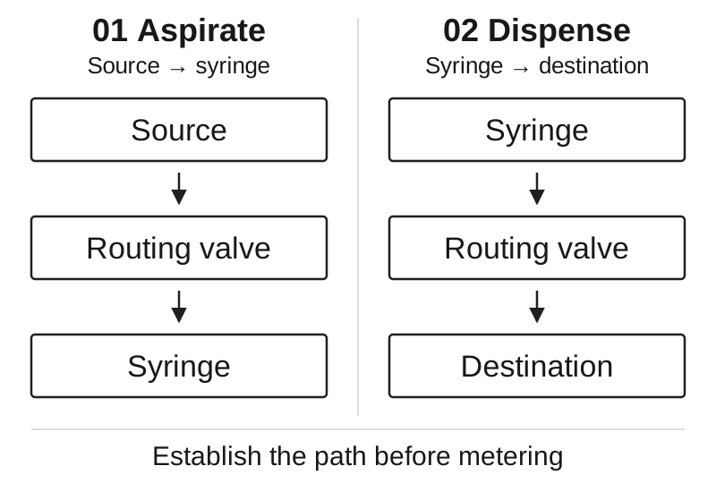
03Which actions are programmable?
A program divides a dispensing task into repeatable actions and retains different settings for different liquids and methods. Aspiration and dispensing may need different speeds: aspiration must accommodate inlet resistance and filling, while dispensing must balance cycle time, outlet pressure, drop release and splashing.
| Control | Purpose | Verify |
|---|---|---|
| Position and stroke | Set nominal aspirated or dispensed volume | Syringe dimensions, calibration and usable travel |
| Speeds and ramps | Coordinate filling, delivery and timing | Resistance, bubbles, residual liquid and pressure changes |
| Delays and valve sequence | Coordinate routing with metering | Path state, completion and timeout handling |
| Repetition, refill and wash | Organize batches and liquid changes | Remaining capacity, shared paths and waste destination |
Depending on the controller and firmware, sequences may run within the module or be scheduled step by step by a host. Integration also requires busy/ready states, completion feedback, timeouts and recovery after power loss. RS232, RS485 and CAN identify communication interfaces; they do not establish a common command set across manufacturers.
04Multiport valves or multiple channels?
A multiport valve increases the number of selectable fluid connections. One syringe may connect to reagent A, then wash liquid and then waste, while still sharing a single metering chamber and normally operating sequentially. Port count is not the number of simultaneous dispensing channels, nor does it prove that any two ports can connect.
A multichannel syringe pump contains multiple metering channels. Confirm whether they move together or independently, whether valves switch separately and which syringe capacities can be combined. Sequential processing of several sources and parallel dispensing into several vessels require different configurations.
Changing the selected source does not remove the previous liquid from a shared syringe, valve cavity or outlet tube. Cleaning must cover the shared segments actually used, followed by a blank or suitable carryover measurement. A fixed number of rinse cycles alone cannot establish cleanliness.
05How do HMD and HLD configurations differ?
FOREACH HMD uses solenoid-valve configurations, while HLD uses rotary-valve configurations. Begin selection with fluid connections, metering-channel needs and installation space. The 30 mm and 60 mm figures describe drive stroke, not volume range or an accuracy grade. Syringe, valve and control options still need to be selected.
| Model | Architecture | Initial selection focus |
|---|---|---|
| HMD3 | 30 mm stroke; solenoid valve; one metering channel | Compact installation, inlet/outlet paths and syringe volume |
| HMD6 | 60 mm stroke; solenoid valves; single/multichannel options | Channel count, motion relationship and volume combinations |
| HLD3 | 30 mm stroke; rotary valve; one metering channel | Space and routing between required sources and outlets |
| HLD6 | 60 mm stroke; rotary valve; one metering channel | Syringe configuration, source selection and wash paths |
Reagent addition and repeated dispensing require attention to dose, batch volume and refill intervals. Sample dilution must coordinate metered amounts, addition order and mixing. Preparation involving several liquid sources needs a suitable valve connection map and shared-path cleaning. These are candidate tasks; suitability must be verified with the actual liquid and instrument workflow.
06How should performance be verified in the instrument?
Evaluate the pump with the intended reservoir, tubing length and bore, valve, dispensing needle and liquid. A water test with short tubing does not cover changes in liquid level, outlet backpressure or reagent properties after installation.
- Fix liquid, temperature, measurement method and repeat count. Measure minimum, routine and maximum target volumes. Gravimetric measurements need the actual liquid density and evaporation control.
- Compare the first dose after priming, intermediate doses and the first dose after refilling to assess changes caused by transitions.
- Run a full batch across expected liquid levels and backpressures; record delivered volume and timing, not just motor position.
- Validate shared-path cleaning in the intended liquid-change order and check the waste route.
- Verify recovery from an empty source, timeout or interruption. Without appropriate sensing, do not assume the module detects these conditions automatically.
Record volume bias, repeatability, cycle time and carryover separately. Include aspiration, valve switching, delays, dispensing, refilling and cleaning in timing, rather than using the fastest plunger travel alone. Save the operating conditions with the results to decide when a liquid, tubing or method change requires revalidation.
07Frequently asked questions
Does a larger syringe cover both larger batches and smaller doses?
Not automatically. The same plunger travel displaces more liquid in a wider syringe. A larger capacity may reduce refill frequency, but minimum reliable volume still depends on the mechanics, seals and installed fluid path. Define minimum and routine doses, batch total and allowable cycle time together.
Can a single syringe provide uninterrupted flow?
Its usable stroke is finite. Once emptied, it normally needs to switch paths and refill, interrupting delivery. For continuous supply, evaluate alternating metering mechanisms or buffering and verify flow and pressure during transitions. A larger syringe may only extend the interval between refills.
Can the existing program be reused when the replacement pump has the same interface?
Not necessarily. Check command format, units, addressing, initialization, valve-position definitions, busy and error feedback, mechanical dimensions and fluid connectors. Even with communication established, revalidate the full aspiration/dispensing cycle and fault recovery.