
What to Do When a Laboratory Waste Aspiration Pump Loses Suction: Troubleshooting Leaks, Filter Blockage, and Liquid Carryover
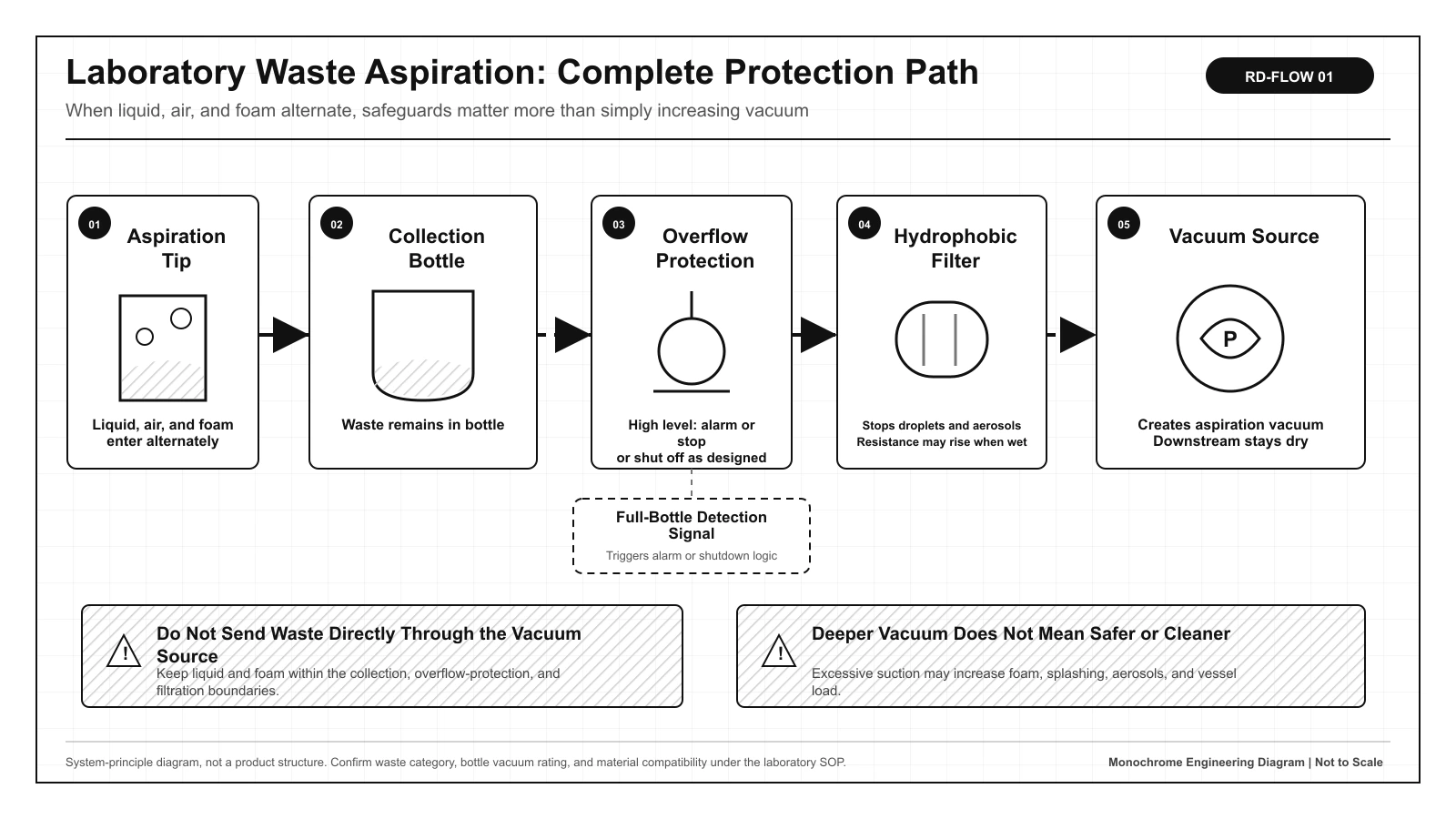
A laboratory waste aspiration pump is normally installed downstream of the collection bottle, overflow protection, and hydrophobic filter. It creates vacuum by removing gas from the bottle. When suction declines, first distinguish a change in the pump itself from a leak, blocked filter, activated overflow protection, clogged tip, or liquid carryover.
Laboratory waste aspiration pumps are also called vacuum aspiration pumps or waste aspiration vacuum pumps. They are commonly used to collect culture media, supernatant, and wash liquid in cell culture, microplate washing, and automated workstations. The pump is not an isolated component; it is the vacuum source for the entire aspiration path.
1. What Does a Laboratory Waste Aspiration Pump Do in the System?
A typical path is aspiration tip → aspiration tubing → collection bottle → overflow protection → hydrophobic filter → aspiration pump. Liquid, air, and foam enter at the tip. Under normal conditions, waste liquid remains in the collection bottle, while the pump removes gas from above the liquid to create a pressure differential between the tip and the bottle.
| Stage | Medium entering the tip | Load seen at the pump | Recommended records |
|---|---|---|---|
| Tip contacts the liquid | Predominantly liquid | Gas is continuously removed from the collection-bottle headspace | Aspiration time, liquid-column height, residual volume |
| Liquid level falls | Alternating liquid and air | Leakage and gas load increase | Pressure waveform, foam height, sound |
| Liquid is depleted | Predominantly air | The operating point shifts to gas pumping and vacuum maintenance | Steady pressure, dry-aspiration duration, temperature rise |
| Abnormal overfill | Liquid or foam crosses the safeguards | Liquid may reach the pump inlet | Liquid level, interlock response time, filter condition |
2. Maximum Vacuum Alone Does Not Define Aspiration Performance
Maximum vacuum indicates the vacuum limit a pump can approach. Free gas flow indicates the scale of gas delivery at low differential pressure. They are not the same operating point. Once tubing, filters, bottle caps, and fittings are installed, actual aspiration speed is determined jointly by the pump curve and system resistance.
S_eq ≈ (V_g / t_build) × ln(p₀ / p₁)V_g is the actual gas-space volume during the test, and t_build is the time for absolute pressure to fall from p₀ to p₁. The result can compare equivalent vacuum-generation performance in the same system, but it is not the pump's nameplate flow. Moisture, leakage, material outgassing, and temperature variation all affect the result.| Observed behavior | More consistent with an external-system issue | More consistent with a pump or drive issue |
|---|---|---|
| The clean, short-tube baseline is normal, but the complete system is slow | Filter, leak, tubing, tip, or overflow protection | Less likely |
| Both the pump-side baseline and complete system decline gradually | Also check power supply and environmental conditions | Inspect valves, diaphragm, drive, or wear |
| The system can build vacuum, but liquid aspiration is still slow | Clogged tip, narrow tubing, lift height, or viscosity | This alone does not prove pump failure |
| Pressure rises rapidly after the pump stops | Leak at the bottle cap, fitting, tubing, or check boundary | Isolate the system in sections before judging |
An engineering selection should include available gas flow at the target vacuum, evacuation time for a defined volume, temperature rise during continuous operation, power conditions, and total system resistance. A description that only says “high suction required” cannot establish the pump's operating point in the actual instrument.
3. Leaks, Filter Blockage, and Liquid Carryover Leave Different Evidence
| Fault | Typical behavior | Safe verification method | Main corrective focus |
|---|---|---|---|
| Leak at the bottle cap or fitting | Target vacuum is never reached and the sound of drawing air persists | Isolate sections and compare pressure–time curves | Seals, threads, tubing, and assembly stress |
| Wet or blocked hydrophobic filter | Suction weakens gradually and pressure drop across the filter rises | Replace with a qualified filter according to the maintenance procedure, then retest | Continue tracing the source of foam, droplets, or contamination |
| Blocked tubing or aspiration tip | One branch is slow while the pump can still build vacuum | Restore the tubing geometry, clean the tip, and retest | Kinks, flattening, crystallization, and protein residue |
| Overflow protection has activated | Aspiration stops suddenly or flow falls sharply near a full bottle | Check the liquid level and reset state according to the SOP | Never bypass the safeguard to continue aspiration |
| Liquid carryover has occurred | The filter is wet, pump sound changes, or exhaust behavior is abnormal | Shut down, isolate, and assess under the contamination-control procedure | Do not assume normal use can resume after air-drying alone |
Use a Pressure-Rise Test to Confirm System Leakage
With the system clean, dry, at a relatively stable temperature, and within the approved maintenance procedure, evacuate it to the specified absolute pressure, isolate the pump, and record the pressure rise in a known gas-space volume. Repeating the test and retaining a new-unit baseline makes gradual seal deterioration easier to detect than judging by sound alone.
q_L = V_gas × (Δp / Δt)q_L is the equivalent gas load obtained from the pressure-rise method. V_gas must be the actual gas-space volume, and Δp must use the change in absolute pressure. Evaporation from a wet bottle, foam collapse, and material outgassing can also raise the result, so first use it for relative comparison under the same conditions rather than applying a universal acceptance limit.4. Material Compatibility Must Cover Waste, Vapor, and Abnormal Droplets
Under normal operation, an aspiration pump primarily contacts gas, but it may still encounter waste vapor, aerosols, and droplets from abnormal carryover. Material assessment must extend beyond the collection bottle and tubing to the pump inlet, wetted pump-chamber materials, diaphragm, valves, and exhaust routing.
| Medium information to specify | Why it matters | What must not be used as a substitute |
|---|---|---|
| Composition, concentration, temperature, and pH | These determine swelling, corrosion, and vapor load | Do not specify only “laboratory waste” |
| Foam, protein, particles, and crystallization | These can block tips, valves, and filters | Do not test only with a beaker of clean water |
| Disinfectants and cleaning procedure | Contact time and mixing sequence can change risk | Do not assess from material names alone |
| Biological hazards and volatility | These determine filtration, exhaust, and maintenance protection | Do not equate gas tightness with biosafety |
Infectious, corrosive, flammable, volatile, or organic-solvent-containing waste must be assessed specifically against the laboratory EHS requirements, waste SOP, and actual medium. The ability to pump gas or handle gas–liquid mixtures does not establish biosafety, explosion protection, or compatibility with every chemical medium.
5. Complete-System Verification Must Combine Normal, Loaded, and Abnormal Conditions
| Test condition | Controlled input | Record at minimum | Purpose |
|---|---|---|---|
| Clean aspiration-pump baseline | Fixed gas-space volume, tubing, power supply, and temperature | Evacuation time, pressure, current, temperature rise, noise | Establish a comparison baseline for the pump itself |
| Actual waste cycle | Actual liquid, foam, dry-aspiration time, and operating cycle | Aspiration time, residual volume, foam height | Verify task completion |
| Filter loading | Defined simulated wetting or contamination condition | Filter pressure drop, evacuation time, alarm | Confirm the maintenance threshold and detectability |
| Controlled minor leak | Introduce a repeatable leak at a designated safe position | Pressure rise, alarm time, change in aspiration | Distinguish normal air aspiration from an abnormal seal |
| High liquid level and foam | Increase liquid level and foam progressively | Interlock response time and whether liquid reaches downstream | Verify the liquid-protection boundary |
| Shutdown and restart | Final installation, post-maintenance condition, and longest shutdown interval | Initial evacuation, recovery time, abnormal-event count | Verify recovery after long-term use |
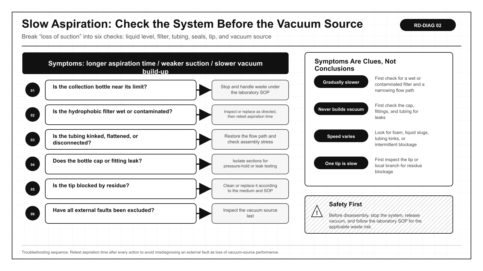
6. Follow These Six Steps When a Laboratory Waste Aspiration Pump Loses Suction
- Stop the system and determine whether an overfill, foam crossover, or liquid carryover has occurred. For hazardous waste, isolate the system according to the SOP first.
- Check the liquid level in the collection bottle and whether the overflow protection has activated. Do not force a bypass.
- Check whether the hydrophobic filter is wet, contaminated, blocked, or installed in the wrong direction.
- Inspect tubing, tips, and upstream branches for kinks, flattening, disconnection, or residue blockage.
- Check the bottle cap, seals, and fittings for leakage, then confirm each section against the pressure–time baseline.
- Only after external faults have been eliminated should you use the clean baseline to inspect the aspiration pump, power supply, drive, and control logic.
7. Engineering Conclusions, References, and Use Boundaries
A laboratory waste aspiration pump is the vacuum source, not the collection bottle. When suction declines, comparing a clean pump-side baseline with the complete-system curve generally locates the problem faster than simply increasing maximum vacuum. Collection, overflow protection, filtration, leak detection, and alarms determine whether an abnormal condition can be stopped upstream of the pump.
Related application: Laboratory automation.
FAQ | Common Questions About Laboratory Waste Aspiration Pumps
Where should I check first when a laboratory waste aspiration pump loses suction?
Stop the system and first determine whether it is overfilled or whether foam crossover or liquid carryover has occurred. Then check overflow protection, the hydrophobic filter, tubing and tips, and leaks at the bottle cap and fittings. Only after excluding external causes should you inspect the pump against its clean baseline.
Why is liquid aspiration still slow even though the pump can build vacuum?
Building vacuum only shows that the gas path reached a certain pressure. A clogged tip, narrow tubing, liquid-column height, deformed tubing, waste viscosity, and filtration resistance can still limit the actual liquid aspiration speed.
Can a wet or blocked hydrophobic filter reduce suction?
Yes. A wet, contaminated, or incorrectly installed filter increases gas-path resistance and commonly lengthens evacuation time and progressively slows aspiration. After replacement, continue tracing the source of foam or droplets.
How can I determine whether the bottle cap, fitting, or tubing is leaking?
Under controlled clean, dry, and temperature-stable conditions, isolate the system in sections and compare pressure-rise curves for a known gas-space volume. Moisture evaporation and material outgassing also affect the result, so compare against a baseline under the same conditions.
Can the aspiration pump continue operating after waste liquid has carried over into it?
Do not assume it can resume operation after air-drying alone. Shut down and isolate the system. In accordance with the medium risk, contamination-control procedure, and manufacturer's maintenance requirements, inspect the filter, tubing, and pump chamber and assess materials, performance, and exhaust safety.
Is maximum vacuum the only selection criterion for a laboratory waste aspiration pump?
No. Also evaluate effective gas flow at the target vacuum, collection-bottle gas-space volume, evacuation time, leakage, filtration resistance, continuous temperature rise, the actual duty cycle, and abnormal-condition safeguards.