
IVD Waste Aspiration: Liquid Pump or Vacuum Pump? Direct vs Indirect Aspiration
Probe washing, reaction-cup cleaning, and routine waste removal in IVD instruments are all described as “waste aspiration.” Yet whether waste passes directly through a liquid pump or first enters a collection bottle while a vacuum pump creates negative pressure leads to entirely different selection logic.
Before selecting a pump, answer four questions: Does waste pass through the pump? Will air continue to enter after the liquid is removed? Does the system require continuous liquid transfer or short-cycle evacuation? Does the waste contain foam, particles, crystallized residue, or corrosive cleaning agents?
1. Map the Waste Path Before Selecting the Pump
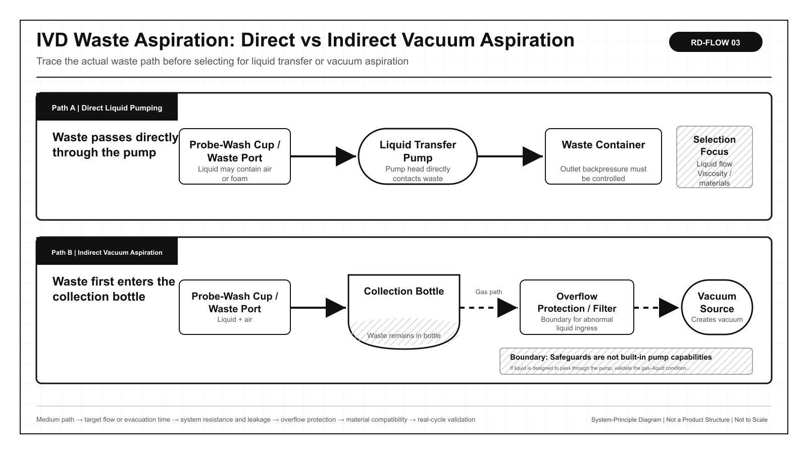
| Concept | Medium primarily contacting the pump | Does waste pass through the pump head? | Core task |
|---|---|---|---|
| Direct liquid pumping | Waste liquid, possibly with entrained bubbles | Yes | Transfer waste directly into the waste container |
| Indirect vacuum aspiration | Air, moisture, and aerosols | Normally no | Create and maintain vacuum in the collection bottle |
| Gas–liquid handling capability | Alternating liquid, bubbles, and air | Depends on the architecture | Handle dry aspiration, liquid slugs, or moisture—not precision metering |
Gas–liquid handling may be used in a direct pumping path or as tolerance for an abnormal event on the vacuum side. It does not eliminate the question of which medium the pump primarily handles, nor does it eliminate liquid-level detection, overflow protection, and filtration.
2. IVD Waste Is Rarely a Stable, Single-Phase Liquid
Waste removal from probes and reaction cups is usually intermittent. Liquid enters when a valve opens, bubbles appear as the level falls, and aspiration may continue after the liquid is gone to reduce residual volume. Surfactants can produce foam, while protein or reagent residue can deposit, crystallize, or block small passages.
| Cycle stage | Medium state | Parameter commonly misinterpreted | What to verify |
|---|---|---|---|
| Liquid entry | Continuous or intermittent waste liquid | Treating free gas flow as liquid flow | Actual transferred volume, backpressure, viscosity, and residual liquid |
| Liquid level falls | Alternating liquid slugs and bubbles | Looking only at average flow | Pressure fluctuation, repriming, and valve timing |
| Dry aspiration | Predominantly air | Assuming dry running has no effect | Permitted dry-aspiration duration, temperature rise, noise, and service life |
| Idle after cleaning | Residue, deposits, or crystallization | Testing only a new pump with clean water | Restart, cleaning recovery, and long-term sealing |
3. Direct Liquid Pumping: A Shorter Path, but the Pump Bears Every Waste Risk
Direct pumping places the pump in the waste path. It suits systems with fewer branches, continuous liquid-transfer requirements, or a need to control liquid delivery directly. The tradeoff is that cleaning agents, sample residue, foam, crystals, and particles all enter the pump head. The diaphragm, valves, pump chamber, and downstream backpressure therefore all become part of validation.
| Dimension | Advantages of direct pumping | Tradeoffs that must be managed |
|---|---|---|
| Architecture | Short path and relatively few components | The pump directly contacts all waste |
| Liquid removal | Can transfer continuously to a waste container | Outlet backpressure and backflow must be controlled |
| Multiple branches | Individual branches are easy to debug separately | More pumps or valve controls may be required |
| Maintenance | No periodic emptying of a vacuum collection bottle | Pump residue, cleaning, and valve deposits become more important |
| Dry aspiration | Can reduce end-of-cycle residual liquid | Confirm the pump tolerates gas–liquid alternation and can reprime |
Direct pumping must be verified for more than whether it can initially draw liquid. Also verify the transition from wet operation to dry aspiration, repriming after drawing air, whether long-term deposits prevent the valves from sealing, and the final residual volume under the worst waste condition.
4. Indirect Vacuum Aspiration: The Pump Is Separated from Bulk Waste, but Safeguards Remain Essential
Indirect aspiration uses a vacuum pump to reduce gas pressure above the liquid in a collection bottle, drawing waste into the bottle through the pressure differential. One vacuum source can serve multiple branches through a valve manifold, and the pump does not need to contact most of the waste directly. However, the container, liquid-level detection, filtration, overflow protection, venting, and valve timing must work together.
| Protection element | Primary purpose | Typical risk if omitted |
|---|---|---|
| Vacuum-rated collection bottle | Contain waste and withstand the pressure differential | Bottle deformation, leakage, or liquid entering the vacuum line |
| Liquid-level detection | Trigger an alarm or shutdown when full | Waste and foam continue moving downstream |
| Overflow protection | Stop abnormal liquid from reaching the pump side | Contamination of the pump, filter, and exhaust |
| Hydrophobic filtration | Limit downstream movement of droplets and aerosols | Rising resistance or loss of downstream protection |
| Venting and pressure release | Release vacuum before maintenance | Splashing when opened or difficulty opening the bottle |
“The pump does not contact waste” is only the design objective under normal operation. Foam, overfill, liquid-level detection failure, and condensation can still allow droplets to reach the vacuum side. Connecting an ordinary gas pump to an empty bottle therefore does not constitute a complete waste aspiration system.
5. When Should Gas–Liquid Handling Be Included in the Selection Criteria?
| Condition that can be evaluated | Capability that cannot be inferred directly |
|---|---|
| Repeated switching between liquid slugs and air near the end of direct pumping | Does not mean the pump can meter samples or reagents precisely |
| Bubbles or foam in probe-wash waste | Does not allow arbitrary foam, particle, or liquid-slug volume |
| Periodic line evacuation and short dry-aspiration intervals | Does not mean performance matches continuous pure-liquid transfer |
| Possible exposure to moisture or a small amount of condensate at the vacuum end | Does not eliminate the need for collection, overflow protection, and filtration |
If liquid is designed to pass through the pump, specify the gas–liquid ratio, liquid-slug duration, dry-aspiration time, particles, and foam. If the pump is downstream of the collection bottle, specify the gas-space volume, leakage, filter resistance, and abnormal liquid-exposure boundary. Both architectures require material validation with the actual medium.
6. Direct or Indirect Aspiration: Select by Task, Not by One Parameter
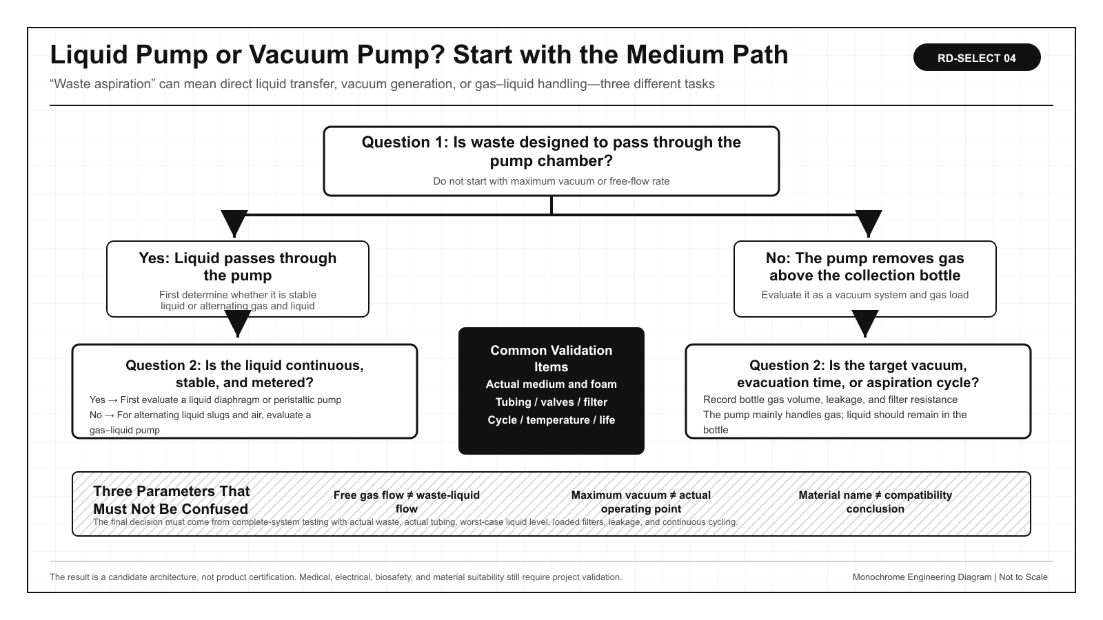
| Selection dimension | Direct liquid pumping | Indirect vacuum aspiration |
|---|---|---|
| Does waste pass through the pump? | Yes | Normally no |
| Continuous liquid removal | Relatively straightforward | Collection-bottle emptying must be considered |
| Expansion to multiple branches | Add pumps or valve controls | One vacuum source can serve multiple branches by valve timing |
| Primary material risk | The pump directly contacts all waste | Moisture, aerosols, and abnormal liquid carryover |
| Primary maintenance point | Residue, valves, and diaphragm inside the pump | Collection bottle, filter, liquid level, and seals |
| Key acceptance tests | Actual transferred volume, dry aspiration, and repriming | Evacuation time, branch interaction, and overflow protection |
Q_cycle = V_waste / t_cycleQ_cycle describes only the average waste demand per cycle. For direct pumping, also cover instantaneous flow, outlet backpressure, and dry aspiration. For indirect aspiration, also cover collection-bottle gas-space volume, evacuation time, leakage, and pressure recovery after a valve opens.7. Six Common Selection Mistakes and How to Prevent Them
| Common mistake | Why it fails | Prevention |
|---|---|---|
| Treating free gas flow as waste-liquid flow | The test medium and resistance are different | Measure evacuation time and residual volume in the actual liquid circuit |
| Comparing only maximum vacuum | Actual speed depends on tubing, valves, filters, and leakage | Record the pressure–time curve of the complete system |
| Sizing only from the incoming wash-liquid volume | A large amount of air enters after the liquid has been removed | Record liquid volume, dry-aspiration duration, and cycle timing together |
| Omitting overflow protection in indirect aspiration | Foam and overfill can reach the vacuum side | Provide liquid-level detection, shutdown, filtration, and secondary protection |
| Relying only on material names | Concentration, temperature, and contact time change the outcome | Perform immersion, cycling, cleaning, and life validation |
| Using a waste pump for precision metering | Waste removal and metering have different objectives | Design reagent metering and waste aspiration as separate functions |
Meaningful complete-system data is not simply “can aspirate” or “cannot aspirate.” It includes evacuation time per cycle, final residual volume, repriming after dry aspiration, interaction between branches, filter pressure drop, collection-bottle evacuation time, material changes, and full-bottle protection response.
8. Installed-System Validation Checklist, References, and Use Boundaries
- Specify cleaning agents, sample residue, foam, particles, crystallization, and any potentially hazardous volatile substances.
- Confirm whether the pump contacts bulk waste or only moisture above the collection bottle.
- Test with the actual tubing diameter, tubing length, valves, filters, and worst-case liquid level.
- Measure evacuation time per cycle, residual volume, dry-aspiration duration, and repriming capability.
- Verify pressure recovery and interaction when multiple branches operate simultaneously or sequentially.
- Verify liquid-level alarms, full-bottle shutdown, overflow protection, venting, and maintenance procedures.
- Complete material-compatibility, cleaning, deposition, continuous-duty-cycle, and service-life validation.
Related application: IVD instrument fluidics.
Related selection guide: IVD waste pump—liquid or gas-liquid diaphragm pump.
FAQ | Common IVD Waste Aspiration Selection Questions
Does deeper vacuum always make IVD waste aspiration faster?
Not necessarily. Actual speed also depends on tubing diameter and length, valves, filter pressure drop, leakage, collection-bottle volume, and liquid properties. Excessive vacuum may also increase splashing and foam.
Can free gas flow be converted directly into waste-liquid flow?
No. The medium, pressure, and system resistance are different. Waste-liquid flow must be measured with the actual tubing, valves, liquid level, and backpressure.
Can an ordinary liquid pump directly aspirate probe-wash waste?
Confirm that the pump tolerates the expected dry aspiration and gas–liquid alternation, can reprime, and has compatible materials. Also validate foam, residue, and long-term deposition.
Can indirect vacuum aspiration guarantee that liquid never reaches the vacuum pump?
No absolute guarantee is possible. Overfill, foam, condensation, or a safeguard failure can still allow liquid to reach the vacuum side, so liquid-level detection, overflow protection, and filtration are required.
Can one vacuum pump serve multiple waste branches at the same time?
It can be evaluated, but test the number of simultaneously open branches, valve timing, collection-bottle volume, pressure recovery, and interaction between branches. A leak in one branch may slow the others.
How should materials be selected when waste contains hypochlorite, surfactants, or protein residue?
Do not rely on material names alone. Use the actual concentration, temperature, contact time, cleaning cycle, and deposits in immersion, cycling, and life tests, and include the pump, tubing, valves, and seals.