
How Do You Build a Pressure Budget for a High-Backpressure Fluid Path? A Foreach 600 kPa Miniature Diaphragm Pump Selection Example
For a high-backpressure fluid path, do not tell a supplier only that you need 6 bar. Break down steady-state pressure losses at the target flow, establish normal steady-state, worst steady-state, pressure-margin, and transient-protection boundaries separately, and then compare them with the candidate pump's controlled curve.
A high-backpressure fluid path usually includes a reservoir, suction tube, pump, valves, fittings, filter, needle or nozzle, and endpoint chamber. Every component can consume pressure differential. The pump must overcome these steady-state losses at the target flow to complete the delivery task.
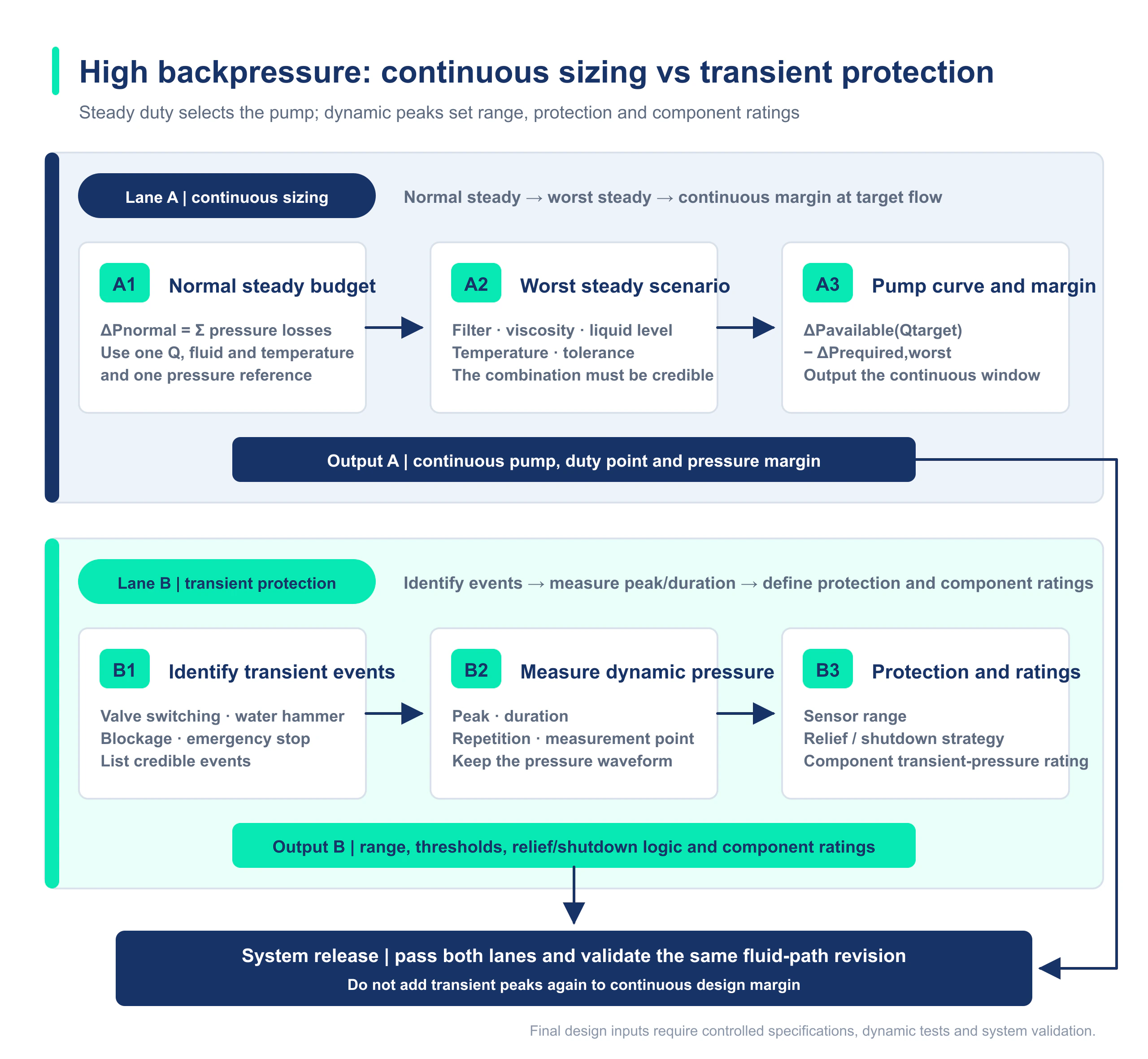
A pressure budget should not collapse normal conditions, worst conditions, design margin, and valve-switching or blockage peaks into one number. Normal and worst conditions establish operating points. Margin indicates the candidate design's tolerance of variation. Transients define sensing, shutdown, pressure-relief, and component-protection boundaries.
1. Start the Pressure Budget with the Complete Fluid Path, Not the Pump
ΔPsteady(Qtarget) = Poutlet,steady(Qtarget) − Pinlet,steady(Qtarget)First standardize gauge pressure, absolute pressure, and sign convention, then calculate inlet and outlet pressure at the same target flow.When the budget is broken down by component, it can include steady suction-side loss, steady discharge-tube loss, local losses through valves and fittings, filter pressure drop, needle or nozzle pressure drop, endpoint chamber pressure, and static-head difference. Only data from the same state and target flow, using a consistent sign convention, may enter one steady-state budget.
2. Provide at Least Twelve Categories of Information for a High-Backpressure Application
| Item | Data to provide | Data source |
|---|---|---|
| Fluid | Name, concentration, temperature, viscosity, and presence of particles or bubbles | Formulation and process conditions |
| Target flow | Minimum, nominal, maximum, and allowable tolerance | Equipment cycle time |
| Reservoir conditions | Liquid-level range, vessel pressure, and whether the first start is dry | Equipment layout |
| Suction tube | ID, length, material, elbows, and fittings | Drawing or physical assembly |
| Discharge tube | ID, length, material, elbows, and fittings | Drawing or physical assembly |
| Valves | Complete model number, bore, Cv, or pressure-drop curve | Supplier data |
| Filter | Complete model number, new-element pressure drop, and end-of-life pressure drop | Supplier data or measurement |
| Needle or nozzle | Complete model number, ID, length, and flow-pressure-drop data | Supplier data or measurement |
| Endpoint chamber | Atmospheric, negative, or positive pressure range | System definition |
| Duty cycle | Continuous or intermittent operation, start-stop frequency, and duration per cycle | Program cycle |
| Transients and abnormal conditions | Valve switching, blockage, start-stop peaks, duration, and protective actions | Dynamic testing |
| Power and control | Voltage range, PWM, current limiting, and feedback | Electrical design |
3. Establish Four Boundaries Separately
1. Normal steady-state operating point
ΔPnormal steady(Qtarget) = Poutlet,normal steady(Qtarget) − Pinlet,normal steady(Qtarget)Use typical liquid level, a new filter, nominal voltage, and fluid at normal temperature to confirm the everyday operating point and control range.2. Worst steady-state operating point
ΔPworst steady(Qtarget) = Poutlet,worst steady(Qtarget) − Pinlet,worst steady(Qtarget)Use minimum liquid level, an end-of-life filter, the fluid-viscosity or temperature boundary, and the highest sustainable endpoint pressure to confirm the worst fluid-path demand.3. Pressure margin
Mpressure(Qtarget) = ΔPcandidate pump allowable boundary(Qtarget) − ΔPworst steady(Qtarget)The candidate-pump boundary must come from a controlled curve or specification for the same fluid, temperature, inlet condition, minimum allowable supply, and duty cycle. The project must define acceptable margin separately.4. Transient and abnormal-condition protection
For peaks caused by valve switching, start-stop events, endpoint blockage, valve misoperation, or pinched tubing, record peak pressure, duration, location, and trigger condition. Review the pressure-sensor range, shutdown threshold, pressure-relief path, and transient allowable boundary of each component separately. These are protection-design inputs, not continuous pump-selection operating points.
| Boundary | What it should include | Purpose |
|---|---|---|
| Normal steady state | Typical liquid level, new filter, nominal voltage, and fluid at normal temperature | Confirm the normal operating point and control range |
| Worst steady state | Minimum liquid level, end-of-life filter, fluid and endpoint-pressure boundaries; review pump capability at minimum allowable supply separately | Confirm target flow, margin, and long-term usability |
| Pressure margin | Candidate pump allowable operating boundary minus worst steady-state demand | Accommodate manufacturing, measurement, aging, and operating-condition variation |
| Transient or abnormal-condition protection | Valve switching, blockage, incorrect switching, pinched tubing, and start-stop peaks | Set sensing, shutdown, pressure-relief, and component-protection boundaries |
4. Illustrative Budget: Add Steady-State Losses, but Treat Transients and Margin Separately
The following demonstrates the method only and does not represent actual customer equipment. Assume a target flow of 220 mL/min. Under the worst sustainable steady-state conditions, measurements or supplier data give a 10 kPa suction-side loss, 18 kPa straight discharge-tube loss, 12 kPa valve loss, 35 kPa end-of-life filter pressure drop, 95 kPa needle pressure drop, and 20 kPa endpoint chamber pressure.
ΔPworst steady(220 mL/min) ≈ 10 + 18 + 12 + 35 + 95 + 20 = 190 kPaThese six items may be added because they belong to the same target flow and the same worst steady state.The 190 kPa result means that a standard 100 kPa-class platform normally should not enter the candidate set directly, but it does not prove that any 600 kPa pump will work. Next, read the candidate pump's controlled curve at 220 mL/min, calculate pressure margin, and review fluid, temperature, inlet conditions, connections, power supply, and duty cycle.
If valve switching creates a separate short-duration peak, record it as an independent transient event and design protection based on its magnitude, duration, and location. Do not add it to the 190 kPa steady-state operating point, and do not add pressure margin to the steady-state equation as another pressure loss.
5. How the Foreach DPL30H Enters the Product Shortlist
Published parameters for the Foreach DPL30H high-pressure liquid diaphragm pump include a 300 mL/min no-load flow, 600 kPa rated pressure, 3 mH₂O self-priming height, and a compression connection for 6 × 4 mm rigid tubing. This makes it a candidate for high-backpressure applications, but selection still centers on the flow available at the target backpressure and whether that point falls within the fluid, temperature, and duty-cycle limits of the controlled specification.
If the needle and filter are the main restrictions, obtain their pressure drops with the actual fluid, temperature, and service-life state. If the main issue is negative inlet pressure or inadequate chamber refill, high outlet-pressure capability does not automatically correct the suction-side condition.
For product selection, see: DPL30H High-Pressure Liquid Diaphragm Pump Selection Guide.
6. After the Pressure Budget, Review the Lowest Allowable Working Pressure in the Entire Path
A pump rated at 600 kPa does not automatically qualify every 6 × 4 mm rigid tube, fitting, valve, filter, pressure sensor, and chamber for 600 kPa working pressure. The component with the lowest allowable working pressure determines the allowable working pressure of the complete fluid path.
- Confirm tubing material, OD tolerance, cut quality, insertion depth, and compression-fitting tightening requirements.
- Confirm allowable working pressure and test pressure, with their applicable conditions, separately for valves, filters, sensors, and chambers; do not mix the terminology.
- Select sensor range, overpressure shutdown, and the pressure-relief path against the normal steady-state, worst steady-state, and transient-protection boundaries.
- Complete pressure-hold, leakage, start-stop, valve-switching, blockage-protection, and life-stage testing.
7. Operating-Condition Template for Direct Use in an Inquiry
| Field | Example entry (replace with actual project data) |
|---|---|
| Fluid and temperature | Purified water, 20–30°C |
| Target flow | Nominal 220 mL/min; minimum 200 mL/min |
| Inlet condition | Reservoir liquid level is 0.4 m below the pump; tubing contains air at first startup |
| Discharge path | 2.0 mm ID, 1.2 m long, with two valves, one filter, and an endpoint needle |
| Steady-state pressure data | Record normal steady state and worst steady state, including filter end of life, separately |
| Transients and protection | Record valve-switching peak, duration, shutdown threshold, and pressure-relief path separately |
| Duty cycle | 45 s per cycle, 1,200 cycles per day, with the ambient-temperature range |
| Control | 24 V, PWM speed control, FG feedback required |
| Validation objectives | Flow, steady-state pressure, transient peak, startup, temperature rise, leakage, and life trend |
Foreach Resources and Evidence Boundary
FAQ | How Do You Build a Pressure Budget for a High-Backpressure Fluid Path?
Must the pressure budget be precise for every fitting?
During preliminary screening, identify the dominant restrictions first. Before design release, review every meaningful reduction and critical component. In a miniature fluid path, even one small-bore fitting can become a major source of pressure drop.
What if end-of-life filter data are unavailable?
First request the flow-pressure-drop curve for the exact model from the supplier. Then establish a boundary through a loading test or equivalent restriction. Data from a new filter alone cannot represent the full service life.
Can a transient pressure peak be added directly to steady-state pressure?
No. Record a transient peak separately by magnitude, duration, location, and trigger condition. Use it to review sensor range, shutdown, pressure relief, and component transient limits. It is not continuous working pressure and does not enter the steady-state operating point.
If the pressure budget is below 600 kPa, will any 600 kPa pump work?
Not necessarily. Also confirm flow at the target pressure, pressure margin, fluid, temperature, inlet conditions, duty cycle, control, connection method, and the lowest allowable working pressure of the complete fluid path.
At what project stage is a pressure budget most useful?
Make a preliminary estimate during concept design. During prototyping, use sensors to measure normal steady state, worst steady state, and transient peaks separately. Before design freeze, establish controlled operating, margin, and protection boundaries.