
Is 100 kPa Enough? How to Determine Whether a Fluid Path Needs a 600 kPa High-Pressure Miniature Diaphragm Pump
100 kPa and 600 kPa are not simply a standard version and an upgraded version. First complete a pressure budget for the entire fluid path at the target flow, then read the candidate pump curve. A higher pressure rating has value only when the application truly has high backpressure.
Application labels such as rinsing, sampling, or needle delivery are not enough to determine a pump pressure class. The same application can fall into completely different operating ranges as flow, tubing ID, filter condition, needle size, or endpoint chamber pressure changes.
Selection should begin with target flow Qtarget and the worst sustainable steady-state pressure differential between the pump inlet and outlet at that flow. Startup and valve-switching transients must then be reviewed separately as protection boundaries, rather than being hidden inside a vague system-backpressure value.
1. Start with the Target Flow Before Selecting a Pressure Class
Fluid-path pressure drop changes with flow. The same tube requires different pressure at 100 mL/min and 300 mL/min, and the same needle changes pressure drop when fluid viscosity changes. Therefore, 'this equipment needs about 100 kPa' is not a complete selection condition unless the corresponding flow is stated.
ΔPrequired(Qtarget) = Poutlet(Qtarget) − Pinlet(Qtarget)The pressure budget must correspond to the target flow. Record the worst steady-state pressure and transient boundaries such as startup, valve switching, or blockage separately.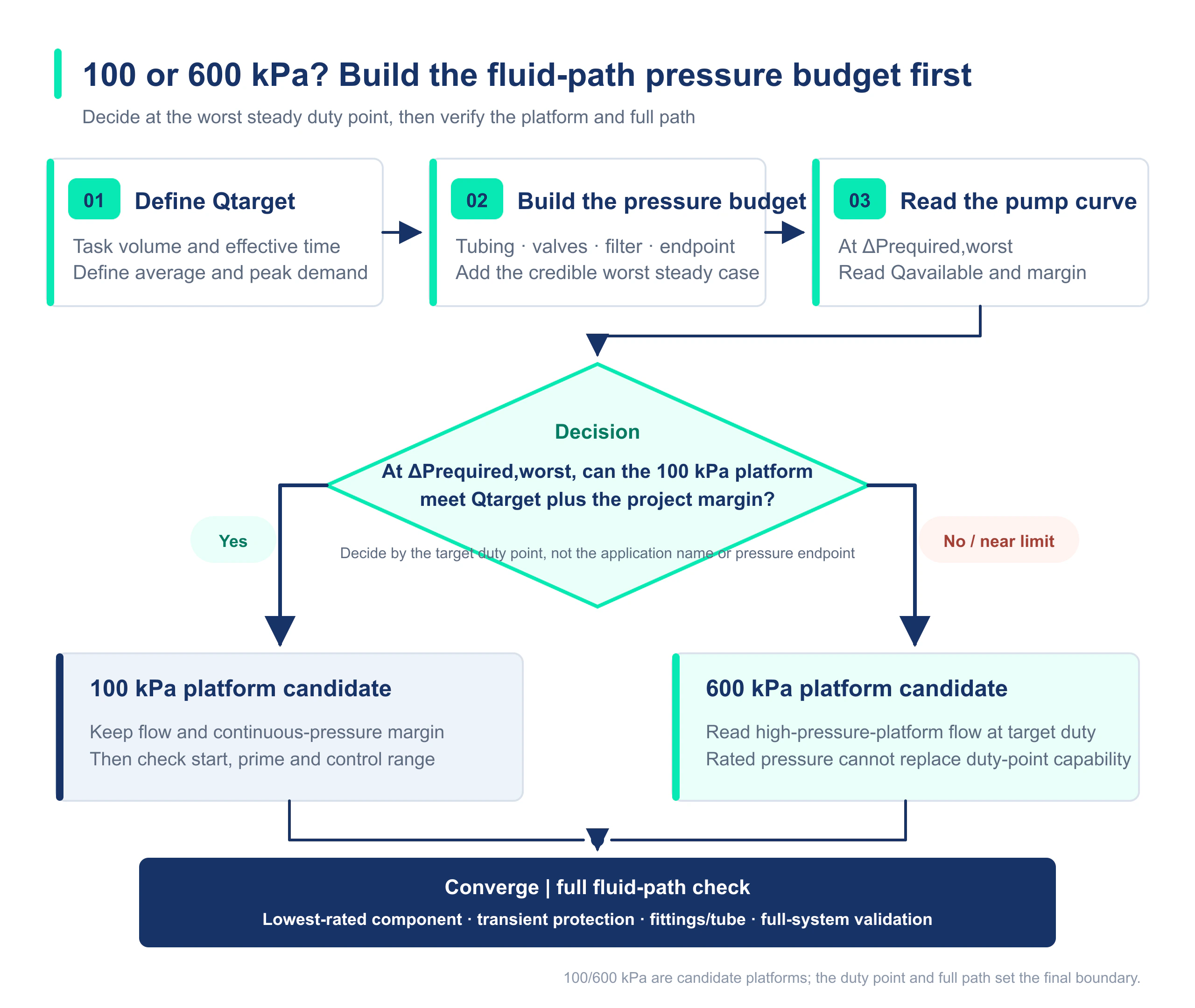
2. Inventory Every Source of Pressure Demand
| Pressure item | Typical sources | Why it cannot be omitted |
|---|---|---|
| Suction-side loss | Suction tubing, inlet valve, filter, and low liquid level | Affects inlet absolute pressure and refill of the pump chamber |
| Straight-tube discharge loss | Narrow tubing, long tubing, and higher viscosity | Increases as target flow rises |
| Local loss | Fittings, elbows, valves, and flow cells | An internal passage may be the narrowest point |
| Filter pressure drop | From a new element to end of life | Can rise substantially during long-term operation |
| Endpoint resistance | Needle, nozzle, and positive-pressure chamber | Often becomes the main source of high backpressure |
| Static and transient pressure | Elevation difference, valve switching, blockage, and start-stop events | Static pressure belongs in the steady-state budget; transients are reviewed as protection boundaries |
3. Which Fluid Paths Are More Likely to Fall in a Lower Pressure Range?
The following characteristics generally indicate lower pressure demand, although calculation and testing are still required: short tubing, larger ID, few valves, an open outlet, low-viscosity fluid, no high-restriction filter or fine needle, and no meaningful suction vacuum caused by reservoir level.
The published rated pressure of both the Foreach DPL30 and DPL60 standard liquid diaphragm pumps is 100 kPa, with no-load flow classes of 300 mL/min and 600 mL/min, respectively. Their suitability is not tied to a fixed industry label; it depends on whether the target operating point lies within the controlled curve and allowable operating conditions.
4. Which Designs Are More Likely to Enter the High-Backpressure Range?
- Fine needles, capillaries, micro-nozzles, or narrow flow cells.
- Long runs of small-ID rigid tubing or multiple abrupt reductions.
- High-precision filters, especially when pressure drop rises near end of life.
- Delivering liquid into a chamber that is already under positive pressure.
- Rapid rinsing or high-velocity jetting that must be completed in a short time.
- Multiple valves, fittings, and sensors in series, whose local losses accumulate.
The published no-load flow of the Foreach DPL30H high-pressure liquid diaphragm pump is 300 mL/min, and its rated pressure is 600 kPa. The 300 mL/min and 600 kPa values do not represent the same operating point. Read a valid revision of the flow-pressure curve to determine how much flow remains at high backpressure.
5. Three Illustrative Conditions: Why Total Pressure Estimates Are Not Enough
| Illustrative condition (not a customer case) | Target flow | Worst steady-state pressure demand | Preliminary assessment |
|---|---|---|---|
| Short tubing, open outlet, and few valves | 180 mL/min | Approximately 40 kPa | A lower-pressure platform may have margin; continue by reading the curve |
| Fine needle, filter, and positive-pressure chamber | 250 mL/min | Approximately 95 kPa | Near the 100 kPa boundary; do not rely on rated pressure alone |
| Fine needle, long tubing, and high-pressure endpoint | 220 mL/min | Approximately 180 kPa | A standard 100 kPa platform normally should not enter the candidate set directly |
The illustrative 95 kPa value does not mean that a 100 kPa pump is guaranteed to work. If 100 kPa is the candidate pump's rated pressure, the target point is already close to the boundary. Flow at that point, filter loading, fluid temperature, sample-to-sample variation, and design margin must also be reviewed. Startup or valve-switching peaks belong in a separate transient-protection review.
6. A High-Pressure Pump Is Not Automatically Better Than a Lower-Pressure Pump
If the fluid path does not require high backpressure, selecting a 600 kPa platform directly can add constraints on connections, material and temperature boundaries, supply power, control strategy, installation space, and cost. For example, published Foreach data list a self-priming height of 6 mH₂O and a maximum fluid temperature of +80°C for the DPL30. The DPL30H lists a self-priming height of 3 mH₂O, a maximum fluid temperature of +40°C, and a 6 × 4 mm rigid-tube compression connection.
Higher pressure is therefore not a universal upgrade. It is a different set of system boundaries intended for high-resistance fluid paths. A high-pressure platform is an effective choice only when the target operating point, fluid, inlet conditions, and duty cycle all match.
7. Four Conditions for Final Release
- Normal and worst steady-state pressure demand at the target flow has been calculated or measured.
- The controlled pump curve shows that the target flow is still met at the worst steady-state condition, with pressure and flow margins defined by the project.
- Allowable working pressure has been reviewed for the tubing, fittings, valves, filters, sensors, and chambers; test or proof pressure is not used in place of allowable working pressure.
- The complete equipment has passed startup, steady-state, valve-switching, blockage-protection, leakage, and long-term operation validation.
Foreach Resources and Evidence Boundary
For a 600 kPa-class product candidate, review the DPL30H high-pressure liquid diaphragm pump series and confirm the required flow at the calculated operating pressure.
Foreach: DPL30H High-Pressure Liquid Diaphragm Pump Selection Guide
FAQ | How Do You Select Between 100 kPa and 600 kPa Miniature Diaphragm Pumps?
If estimated system backpressure is 80 kPa, is a 100 kPa pump sufficient?
The two values alone are not enough. Confirm the target flow corresponding to 80 kPa and whether it represents the worst steady-state condition, then read the flow and margin at that point from the controlled pump curve.
Can a 600 kPa pump solve every insufficient-flow problem?
No. If the cause is a suction leak, valve fault, inadequate power supply, fluid viscosity, or insufficient inlet refill, a higher-pressure platform may not solve it and can introduce new system constraints.
Does a fine needle always require 600 kPa?
No. Pressure demand depends on the needle ID, effective length, target flow, fluid viscosity, and endpoint pressure. Use supplier pressure-drop data, calculations, or measurements.
Why can a 100 kPa pump not maintain its no-load flow at 100 kPa?
No-load flow and rated pressure are normally different performance endpoints. Flow generally decreases as pressure differential across the pump increases, so the flow corresponding to the target pressure must be read from the curve.
Why must the lowest allowable working pressure of the complete fluid path be reviewed?
The component with the lowest allowable working pressure determines the system's allowable working pressure. Proof or test pressure serves a different verification purpose and cannot replace allowable working pressure for tubing, fittings, valves, filter elements, or chambers.