
How to Configure Instrument Tubing Assemblies and Generate 2D Drawings
A reagent line inside an analytical instrument needs a tube material, an inner and outer diameter, a finished length and two mating connections. A valve and a fluidic module can have different threads or sealing surfaces. The FOREACH tubing assembly configurator lets you set ends A and B independently, preview the assembly and generate a 2D selection drawing with dimensions, fitting models and a bill of materials. Engineering, assembly and purchasing can review the same PDF revision.
01What parameters does the tubing assembly configurator need?
Edit the FEP example above, or enter your own parameters from the fluidic schematic and the drawings of both mating ports.
View saved configurations on the tubing assembly product page
- Select tubing material and size. The configurator lists the available sizes for the selected material as OD × ID. Match the outside diameter (OD) to the fittings and accessories. Select the inside diameter (ID) for the required flow resistance and internal volume.
- Enter finished length L and its tolerance. Use the planned route to determine the length. During drawing review, agree on the two measurement references. For a routed bend, document the measurement path and the allowance needed for assembly.
- Configure ends A and B separately. Identify the mating component at each end, then select the connection type, fitting series, thread and material. In a double-ended assembly, set both ends independently. In a single-ended assembly, configure end A and specify any requirements for the free tube end at B.
- Specify accessories and labels. Check the appropriate backing washers or other hardware for each connection. Label similar-looking lines so assemblers can identify them against the schematic. Enter your customer part number in the drawing details if one has been assigned.
02How do you configure a tubing assembly with different ports at each end?
Start with the mating port drawings and verify each thread, sealing face and installation clearance. The tool offers flanged, ferrule and compression-ring connections, with compatible hardware based on tube OD and end selection. In a flanged connection, the threaded fitting applies the clamping force and the tube flange seats against the flat-bottom port. Check that the flange and washer load in the intended position once the fitting is engaged.
Read the flanged tubing assembly selection guide
| Parameter | Example setting |
|---|---|
| Tube material and size | Clear FEP, OD 1.6 mm, ID 0.3 mm |
| Finished length | L = 250 mm, ±5 mm tolerance |
| End A | Flanged, 1/4-28 UNF, fitting HFL-U28-16-PV-N with SUS backing washer |
| End B | Flanged, M6×1, fitting HFL-M6-16-PV-N with SUS backing washer |
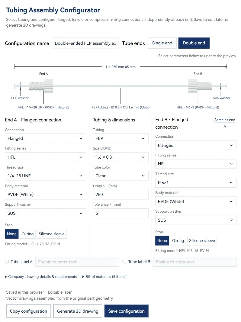
Compare the assembly preview and bill of materials against the fluidic schematic. The example uses illustrative dimensions and tolerance. For your instrument, specify them for the actual media, flow, routing and assembly requirements.
03How do you read the generated 2D tubing assembly drawing?
Select “Generate 2D drawing”, then “Download PDF”. Fitting outlines reference the original part drawings. The sheet updates the tube size, finished length and bill of materials to match your configuration. In this example, it shows 250 ±5 mm and both fitting part numbers for comparison with the mating port drawings.
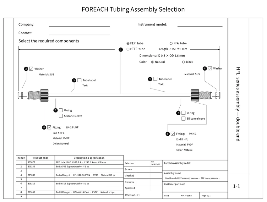
- Engineering checks the connections and dimensions. Verify thread and seal type at both ends, confirm the length references and check routing, bend clearance and tool access in the instrument layout.
- Assembly checks orientation and hardware. Identify the destination of each end, check the washers and other hardware, and confirm that the label text and placement help operators identify the line.
- Purchasing checks the revision and parts. Match the configuration name and revision to the customer part number. Include the target quantity and mating port drawings with a quote or prototype request.
Generating the drawing saves the configuration in the current browser. You can reopen it or save a separate version. Share the PDF for the revision under review. If the fittings or length change, update the configuration and generate a new PDF.
04What should you confirm before prototyping a custom tubing assembly?
Use the selection drawing for design review or a quote request. Before prototyping, provide the mating port drawings, length references, process and cleaning fluids, operating temperature and pressure or vacuum, sample quantity and acceptance criteria. Include an installation drawing if space is restricted. FOREACH can review the configuration and formal drawing with you. Validate sealing, flow and fit in the instrument under the intended operating conditions.