
Leak Testing: Identifying and Preventing Virtual Leaks
During final inspection of gas-tight components or assemblies, measured leakage may fluctuate around the acceptance limit: one test reads low and the next reads higher. Vacuum equipment and instrument fluid circuits operating below atmospheric pressure may show a similar problem—the leak detector finds no definite location, yet evacuation takes longer and the required operating pressure remains out of reach.
Look for gas sources inside the system as well as openings to the outside. Gas trapped during manufacture or assembly may escape only through a restricted passage. This is a typical trapped-volume virtual leak. Material outgassing, moisture desorption and re-evaporation of residual liquid can produce similar symptoms and should be assessed separately.
01How do real, external, internal and virtual leaks differ?
These terms describe different aspects of leakage. Real versus virtual mainly identifies the gas source; external versus internal identifies the path. They are not four mutually exclusive categories. Establish where the gas originates and where it goes before selecting a test method.
- Real leak: gas flows from higher to lower pressure through an actual hole, crack or sealing gap. A leak detector can locate it when sensitivity, tracer-gas access and response time are appropriate.
- External leak: gas crosses the boundary between the system and its surroundings. In a vacuum system, outside gas usually enters the system; in a positively pressurized fluid circuit, fluid may escape to the outside.
- Internal leak: gas passes between chambers or lines that should be isolated, for example through a closed valve. Isolate sections, check pressure holding or pressure rise, and introduce tracer gas on the appropriate side according to the test arrangement.
- Virtual leak: gas stored in an internal dead space enters the vacuum chamber slowly through a low-conductance path, mimicking a persistent leak. Outgassing, desorption, re-evaporation and permeation also increase gas load and are sometimes grouped under this term in practice; distinguish them during diagnosis.
For a real leak, investigate the leakage path. For a virtual leak, investigate stored gas and internal sources of gas release. No response to helium spraying means only that no corresponding signal was detected under the current test conditions; it does not prove that the system has no real leak.
02Why can a virtual leak slow pump-down without a helium signal?
A longer, narrower connection between a trapped volume and the chamber generally has lower conductance, so the stored gas escapes more slowly. The chamber can already be at low pressure while gas continues to enter from the pocket, producing a long tail on the pump-down curve.
q_total ≈ S_eff × p
Approximate steady gas balance: q_total is total gas load in mbar·L/s, S_eff is effective pumping speed at the chamber in L/s, and p is absolute pressure in mbar. Use this simplified relationship only where pump base-pressure effects are negligible and gas load is approximately steady. The pump's nameplate flow is not automatically S_eff.
Increasing effective pumping speed may lower chamber pressure for the same gas load, but it does not remove the trapped volume. Between two welds, a sealed outer weld can prevent externally applied helium from reaching a pocket, while a small path through the vacuum-side weld lets stored gas escape into the chamber. Abnormal pressure and no clear helium response can therefore occur together.
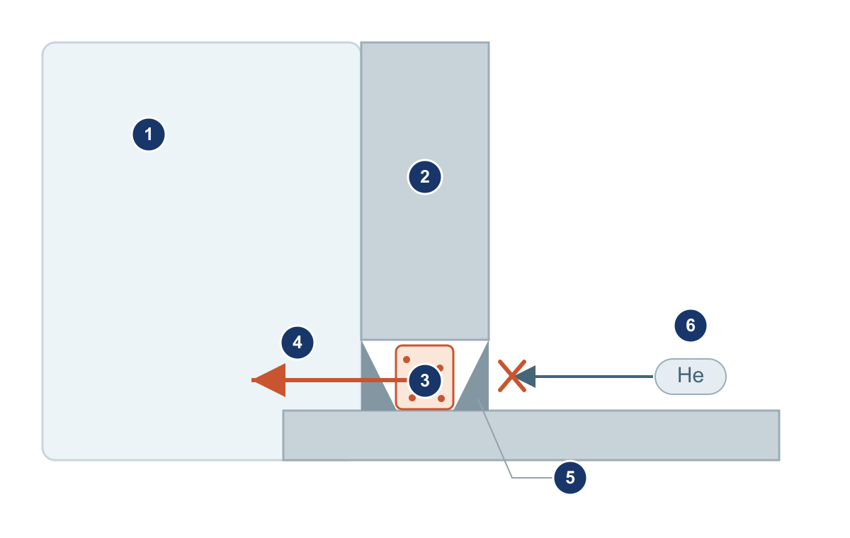
Some dead spaces refill whenever the system is vented to atmospheric pressure, so the next pump-down develops a similar tail and may be mistaken for a stable real leak. Adsorbed moisture or condensate can also remain on colder surfaces and repeatedly desorb or re-evaporate, extending evacuation time.
03Which structures can trap gas and create virtual leaks?
These virtual leaks often originate in design or assembly. Look for both a gas-storage volume and a restricted path to the low-pressure side. A blind hole or two seals alone is not enough to diagnose the fault.
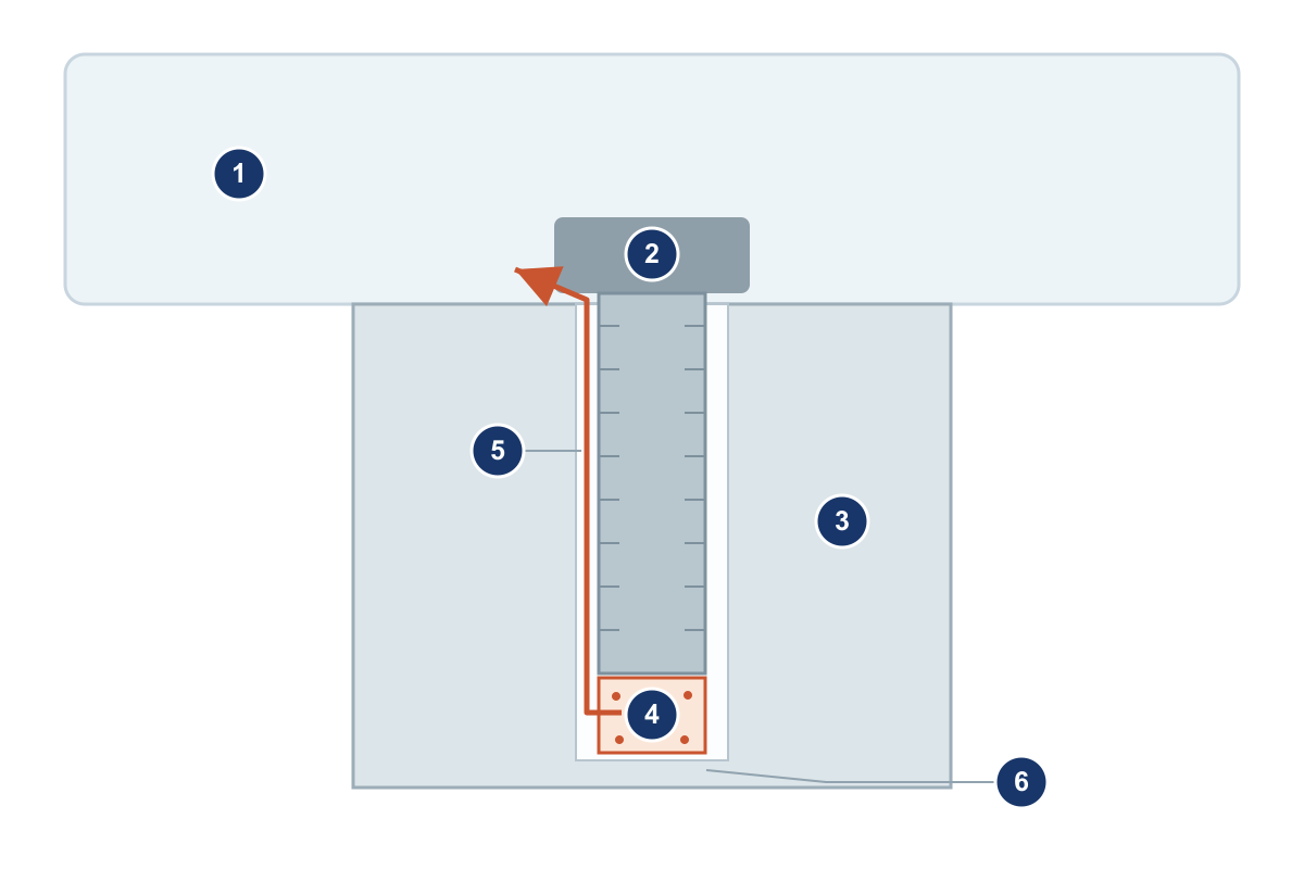
Blind tapped holes: gas beneath a screw escapes through thread clearances
A screw in a blind tapped hole can leave gas trapped below its end. Without a dedicated vent path, gas must escape slowly along the thread clearance into the chamber, while external helium cannot reach the bottom directly. Suitable vented screws or vent holes can help. Because venting changes the screw cross-section and load capacity, mechanical strength must also be checked.
Double welds, tandem seals and flange interfaces: gas between two barriers
- Double fillet welds: an airtight outer weld and a small vacuum-side path can enclose a gas pocket. Define the sealing boundary and vent path during design. Intermittent welding or a dedicated vent arrangement must be assessed against mechanical loading, cleanliness and sealing requirements.
- Tandem seals: gas can remain between two O-rings if the intermediate space has no vent or monitoring passage. External helium may not reach the inner seal. Where the design permits, provide an intermediate venting, pumping or test connection and verify each seal separately; do not add arbitrary grooves that compromise sealing.
- Flanges and gaskets: unsuitable clamping, local contact or gasket deformation can create poorly vented gaps. Control compression and tightening according to the assembly requirements instead of relying on greater clamping force to compensate for contact or venting problems.
04How can material and surface outgassing resemble a virtual leak?
Materials and surfaces can release gas even without a trapped cavity. Their treatment differs from correcting a geometric dead space: material selection, cleaning, drying and an appropriate bake-out address some outgassing sources, whereas trapped volumes often require a better vent path.
- Grease, seals and cleaning residues: retained water, air, solvents and gases inside materials can contribute gas through desorption, diffusion or evaporation. Select materials for the target vacuum level and control unnecessary quantities and residues.
- Vapor pressure and temperature: gas release from lubricants, oil and water depends on temperature. High- and ultrahigh-vacuum designs also require assessment of metals, solder and surface finishes. Suitability for an ordinary liquid circuit does not establish suitability for vacuum service.
- Anodized and porous layers: porous surfaces offer more opportunities for adsorption and gas retention. Suitability depends on the actual treatment process, cleanliness and target pressure; corrosion resistance alone does not establish vacuum performance.
- Ceramics, metals and glass: ceramic porosity and density depend on processing. Even dense substrates acquire adsorbed surface layers after exposure to air. Baking can reduce some gas loads in compatible materials, but it does not repair through-pores, cracks or real leaks.
Cleaning, drying and bake-out conditions must stay within the limits of seals, adhesives, sensors and other components. Do not apply one high-temperature treatment to an entire instrument fluid circuit merely to accelerate gas removal.
05How do pump-down curves and rate-of-rise tests help diagnose virtual leaks?
Compare pressure versus time with a healthy-system baseline while keeping chamber volume, pump, valve positions, piping, temperature and venting history as consistent as possible. Slower pump-down followed by a similar ultimate pressure raises suspicion of outgassing or a virtual leak. A higher pressure plateau may result from a real leak, continuing outgassing or changed pumping performance; it is not a diagnosis by itself.
For a rate-of-rise test, evacuate the chamber, isolate it from the pump and record absolute pressure over time. With stable volume and temperature and other influences controlled, a fairly constant pressure-rise slope suggests a continuing gas source; a decreasing slope supports outgassing or gradual emptying of a trapped space. Continue pumping, then repeat the same pressure-rise interval. Real leaks and outgassing can coexist.
q_apparent ≈ V × Δp / Δt
V is the effective isolated gas volume in L, Δp is the change in absolute pressure in mbar, and Δt is time in s; q_apparent is in mbar·L/s. Use only with approximately stable volume and temperature. Until real leakage, outgassing, trapped gas and isolation-valve leakage have been separated, this is an apparent gas load—not a confirmed external leak rate.
| Observed behavior | Initial possibilities | Next checks |
|---|---|---|
| Pump-down is slower, but long pumping approaches the previous ultimate pressure | Outgassing or a trapped-volume virtual leak; also check the pumping path | Check the pump and valve positions, cleanliness, dryness and dead volumes; treat only within material limits |
| Pressure plateaus higher and repeated rate-of-rise slopes remain fairly constant | A real leak or another continuing gas source | Verify temperature and effective volume, isolate sections and locate leaks using an appropriate tracer-gas method |
| After valve closure, pressure on one side still affects the isolated low-pressure chamber | Isolation-valve leakage or leakage between chambers | Control both sides separately and perform sectional pressure checks; apply tracer gas to the suspect side as appropriate |
| Static testing appears normal, but a leak response appears during motion | A moving seal or a change in mechanical loading | Test during the specified motion and pressure differential; inspect the stem, seals and connection loads, and assess suitable bellows isolation if needed |
| Pump-down slows after humid gas exposure or a long period open to air | Water adsorption, desorption or re-evaporation | Check the gas supply and venting method; clean, dry and extend pumping or bake only within component limits |
If readings fluctuate, also check detector calibration, background, range, tracer-gas access and waiting time. Treat a missing helium response as useful evidence only after confirming that the test method can reach and resolve the suspected location.
06How can design and assembly reduce virtual leaks?
Review the geometry by asking where gas can be stored and how it can escape. Give particular attention to blind tapped holes, welds on both sides, tandem seals and flange interfaces. A dead space does not automatically cause a virtual leak, but an unclear evacuation path warrants assessment.
Review the process by asking what materials and surfaces can release, and how those sources will be treated. Define cleaning, drying, storage and compatible degassing procedures for moisture-retaining surfaces, lubricants, residues and porous layers before assembly. Retain pump-down and pressure-rise baselines after assembly to help distinguish contamination, structural changes and real leaks later.
Connections in instrument fluid circuits under vacuum also need checks of seal location, tube fit and spaces created during assembly. The FOREACH rigid-tubing fittings linked below are examples for comparing fluid connection structures. These vacuum schematics do not establish a high-vacuum or ultrahigh-vacuum rating or a measured leak rate for those products; confirm selection against the model documentation and actual operating conditions.
Virtual leaks are usually easier to address during design. Checking trapped volumes, vent paths and material condition early can reduce repeated leak testing, disassembly and cleaning after assembly.
07Related reading and technical references
- Rigid-tubing fitting selection: connection design, installation and maintenance
- Fitting material selection: body, seals and media
- Pfeiffer Vacuum Knowledge Book: connections and venting blind holes
- Pfeiffer Vacuum Knowledge Book: materials and surface outgassing
- Leybold Vacuum Fundamentals: pressure-rise and pressure-drop tests