
Thread-to-Barb Fitting Selection: Threads, Seals and Tubing Sizes
A thread-to-barb fitting connects a threaded port to flexible tubing. One end screws into a pump, valve, manifold or mating fitting; the other enters the tubing, whose contact with the barb provides sealing and retention. Common terms include threaded hose barb fitting and threaded-to-barb adapter.
Specify thread, port sealing structure and tubing ID together. '1/4 to 3.2' is incomplete: 1/4 can refer to different thread standards, while 3.2 might mean tubing ID, OD or fitting bore.
FOREACH SA straight and SAL elbow fittings use thread sealing with PTFE tape or compatible thread sealant. SB straight, SBS short straight and SBR rotary straight fittings use bottom-face contact sealing without tape or sealant. SC has M6×1 or 1/4-28 UNF female threads, typically receiving a mating rigid-tube fitting. PP, PA, POM and PVDF availability depends on the complete model.
01How do thread-to-barb fittings seal at the port and tubing ends?
SA/SAL use auxiliary material in the engaged threads to close leakage paths. SB/SBS/SBR use thread-generated axial force to press the bottom shoulder face against the mating port face. Their threads primarily retain the fitting; keep the actual bottom sealing face clean and protected.
At the tubing end, the wall stretches over the barb and conforms to it for sealing and retention. Check thread and sealing structure at the equipment end, and ID, material, insertion depth and retention at the tube end. Tightening alone does not address both.
- Equipment portThread standard, port depth and sealing face
- AdapterThread-end sealing structure and internal passage
- Flexible tubingID, wall thickness, material and barb fit
Tightening the equipment thread will generally not fix leakage at the barb root. Adding a hose clamp cannot repair a scratched port sealing face. Locate the leak first, then inspect the relevant dimensions, surfaces and assembly.
02How do UNF, NPT, metric and G threads relate to the sealing method?
| Full thread designation / model code | Thread form | Series and thread gender | Equipment-end sealing |
|---|---|---|---|
| 10-32 UNF/U32 | Unified fine parallel thread; 32 threads per inch | SA-U32, SAL-U32: male | SA/SAL: engaged threads with PTFE tape or thread sealant |
| 1/4-28 UNF/U28 | Unified fine parallel thread; 28 threads per inch | SA, SAL, SB, SBR: male; SC: female | SA/SAL: thread seal; SB/SBR: bottom-face seal; SC: determined by the mating rigid-tube fitting and sealing parts |
| 1/8-27 NPT/1/8NPT | National Pipe Taper thread; 27 threads per inch | SA-1/8NPT, SAL-1/8NPT: male | Thread seal with auxiliary material; do not apply the non-NPT plastic-thread torque |
| 1/4-18 NPT/1/4NPT | National Pipe Taper thread; 18 threads per inch | SA-1/4NPT: male | Thread seal with auxiliary material; follow NPT assembly requirements |
| M5×0.8/M5 | Metric parallel thread; nominal diameter 5 mm, pitch 0.8 mm | SB-M5: male | Bottom shoulder face contact; no tape or sealant |
| M6×1/M6 | Metric parallel thread; nominal diameter 6 mm, pitch 1 mm | SB-M6, SBS-M6: male; SC-M6: female | SB/SBS: bottom-face seal; SC: determined by the mating rigid-tube fitting and sealing parts |
| G1/8/G1/8 | British Standard Pipe Parallel thread | SA-G1/8: male | Listed as an SA thread-sealing model; follow its auxiliary sealing requirements |
U32 means 10-32 UNF and U28 means 1/4-28 UNF. The '10' is a screw-size designation, not 10 mm. The number after the hyphen in UNF/NPT specifies threads per inch; after × in M5×0.8/M6×1 it specifies pitch in millimetres. 1/4-28 UNF cannot interchange with 1/4-18 NPT, nor G1/8 with 1/8-27 NPT.
SA-X32 is a separately listed sloped-thread variant, not SA-U32's 10-32 UNF or an assumed NPT. Provide its complete model and port drawing rather than '32 thread'. The table maps listed models; it does not imply every series offers every thread, material and tube size.
What is the difference between SA thread sealing and SB bottom-face sealing?
SA/SAL seal in the thread engagement using PTFE tape or fluid-compatible sealant. Wrap in the thread direction and control quantity to keep debris or excess sealant out of the passage. Thread sealing does not mean all models are tapered: SA-U28 is parallel UNF, while SA-1/8NPT is tapered NPT.
| Comparison with identical threads | SA-U28-32D-PP-N | SB-U28-32-PP-N |
|---|---|---|
| Shared specifications | 1/4-28 UNF male; 3.2 mm ID tubing; PP | 1/4-28 UNF male; 3.2 mm ID tubing; PP |
| Actual sealing location | Thread engagement | Bottom shoulder face against the mating port face |
| Auxiliary sealing material | PTFE tape or compatible thread sealant | No tape or sealant |
| Mating port requirements | Matching thread and model-specific thread-sealing assembly | Matching thread plus bottom-face contact and compression at the correct depth |
Specify '1/4-28 UNF male + thread seal' or '+ bottom-face seal', then tubing ID and material. SC-U28/SC-M6 female receivers usually connect a rigid-tube fitting to flexible tubing. Determine their seal from the mating fitting and sealing parts; do not automatically apply SA's tape method.
03How do tubing ID, barb OD and bore differ on a thread-to-barb fitting?
| SA-U28-32D dimension | Catalog value | Purpose |
|---|---|---|
| Mating tubing ID | 3.2 mm | Select tubing termination size |
| Bore A | 2.4 mm | Check the passage; bore alone does not establish operating flow |
| Maximum barb OD B | 4.5 mm | Evaluate insertion with tubing material, wall thickness and tolerances |
These three dimensions belong to one fitting but serve different purposes. Specify 'SA-U28-32D-PP-N, 1/4-28 UNF, for 3.2 mm ID tubing', with tubing OD, material and port drawing. Its bore is smaller than the tube ID; include that local restriction in the complete fluid-path assessment.
Equal ID does not guarantee equal assembly behaviour. Hardness, wall thickness and softness change the response to the lead-in and barb profile; temperature, sustained compression and repeated removal affect retention. Select clamps for assembled OD and usable position; excessive clamping cannot correct a wrong size.
For C/F/D/V/X codes and tubing fit, see Barb profiles, tubing fit and clamping
To compare crest OD with tubing ID, see Barb expansion calculation and tolerance analysis; For PP, PA and cleaning conditions, see Fitting material selection.
04How do SA, SAL, SB, SBS, SBR and SC thread-to-barb fittings differ?
| Configuration and example model | Interface and material | Connection function |
|---|---|---|
| SA-U28-32D-PP-N | 1/4-28 UNF parallel male; 3.2 mm ID tubing; PP | Straight thread seal with PTFE tape or compatible sealant |
| SAL-U32-32D-PP-N | 10-32 UNF parallel male; 3.2 mm ID tubing; PP | Elbow thread seal; changes tube direction, using the same sealing principle as SA |
| SB-M5-32D-PP-N | M5×0.8; 3.2 mm ID tubing; PP | Straight bottom-face seal; match port bottom and depth |
| SBS-M6-32D-PP-N | M6×1; 3.2 mm ID tubing; PP | Short straight bottom-face seal; S means short, with port depth and bottom still matched |
| SBR-U28-32-PP-N | 1/4-28 UNF; 3.2 mm ID tubing; PP | Rotary straight bottom-face seal; R means rotary and does not change the port sealing category |
| SC-U28-32D-PP-N | 1/4-28 UNF female; 3.2 mm ID tubing; PP | Female receiver, usually for a rigid-tube fitting; match tube termination and sealing parts |
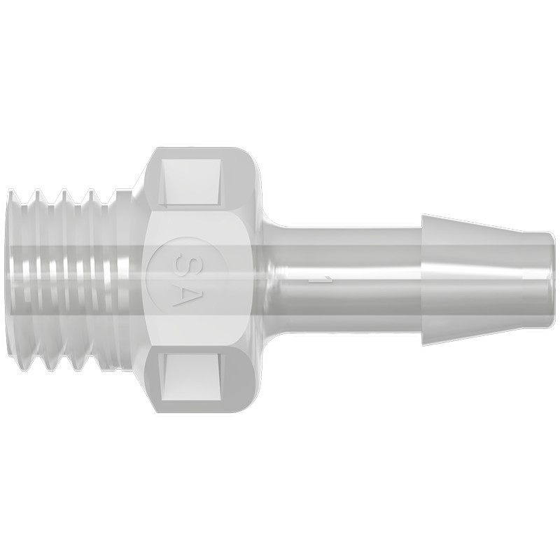
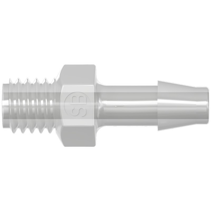
An elbow must face the correct direction after installation. Backing off a sealed joint by half a turn can disturb sealing. SBR's rotary feature is not evidence of continuous high-speed rotary-union capability; continuous rotation requires specified speed, life, pressure and sealing performance.
05How do you select an M6 thread-to-barb fitting for 3.2 mm ID tubing?
Suppose an instrument wash circuit has an M6×1 female flat-bottom port, 3.2 mm ID tubing and space for a straight outlet. SBS-M6-32D-PP-N is a candidate: PP body, bottom-face seal and matching initial thread/tube requirements.
- Port section: verify M6×1, usable thread length, depth and sealing area so the faces meet correctly; merely being able to screw it in is insufficient.
- Tubing: record OD, material, hardness and tolerances for the 3.2 mm ID tube. The catalog gives a 4.5 mm crest and 2.4 mm bore for assembly and passage assessment respectively.
- Fluid: assess both the wash fluid and subsequent cleaning agents against PP and the tubing at actual concentration, temperature and contact time.
- Space: allow tool access and tube bend radius, avoiding side loading or contact with adjacent parts.
- Assembly: keep SBS bottom shoulder and mating port face clean; use no tape or sealant. Establish tightening requirements for the model and port material, then insert and support the tubing.
- Performance: test leakage at specified pressure, temperature and start/stop conditions, and verify target flow. Add vacuum sealing checks for suction service.
If the port is actually 1/4-28 UNF, reselect thread and seal. If '3.2 mm tubing' means OD, determine its ID again. This is a selection example, not validation in a specific instrument.
SBS-M6-32D-PP-N specifications and drawing enquiry
Use the M6 selection process above to define reagent and wash-line connections. These application guides explain the associated fluidic tasks.
06How are thread-to-barb fittings installed, and which sealing materials and tools are needed?
- Check and clean: verify the complete model, port threads and sealing faces; remove debris and inspect the barb for burrs, scratches and cracks.
- Seal by series: apply PTFE tape in the thread direction or compatible sealant to SA/SAL, controlling amount and location. Clean SB/SBS/SBR bottom sealing faces and use no tape or sealant.
- Align before tightening: confirm smooth engagement, then follow model and port-material requirements. Stop and inspect abnormal resistance; do not force crossed threads.
- Use suitable tools on the designated surfaces. Where torque control is required, choose an appropriate-range torque tool; do not grip the barb or tubing with pliers.
- Prepare tubing: cut square, remove debris and push axially to the specified position. Avoid repeated rocking that enlarges the end.
- Support and retest: support tubing, fit suitable clamps if needed, then check leakage, air ingress, retention and flow under full operating conditions.
The assembly note for this series' PP, PA and POM plastic threaded fittings gives 0.25–0.30 N·m (±0.05 N·m), excluding NPT. Do not extend it to PVDF, metal fittings or other structures; also check port material and model requirements. NPT follows its own procedure. Record tool range, setting, sealing material and leak-test conditions for production.
Stop and depressurize before removal. Reused tubing ends may be stretched, indented or cracked; inspect and replace or prepare them as required by maintenance. Do not mask an excessively tight fit with unapproved grease, solvents or heating.
07How do you troubleshoot leakage, air ingress or reduced flow?
| Symptom | Check | Verify after correction |
|---|---|---|
| Leak near threads | Thread standard, sealing method, auxiliary material and cross-thread damage | Reassemble correctly and retest; avoid continued tightening |
| Bottom-face fitting still leaks | Port depth, face shape, scratches, debris and actual face contact | Compare both drawings; clean or replace damaged parts and leak-test |
| Leak at barb/tubing junction | Wrong ID, damaged tube end, insertion depth or barb damage | Replace unsuitable tube or fitting; check sealing and retention |
| Bubbles during suction with no external wetness | Vacuum air ingress, upstream supply and other leak locations | Check vacuum sealing section by section; a positive-pressure test alone is insufficient |
| Tubing loosens after operation | Heat-induced softening or relaxation, pressure peaks and tube tension | Recheck material, barb fit, support and clamping |
| Flow falls after replacing the fitting | Smallest passage, intruding sealant, debris or sharp bends | After cleaning, compare flow and differential pressure at the original duty |
Record complete model, tubing specification, port drawing revision, fluid, pressure, temperature, test duration and assembly method. Define cycle count, loads and acceptance criteria before disconnection or retention testing so sample validation becomes reproducible purchasing and inspection requirements.
08Thread-to-barb fitting FAQs
Does 3.2 mm mean tubing ID or OD?
In these model tables it means mating tubing ID, not crest OD or bore. SA-U28-32D, for example, takes 3.2 mm ID tubing, with a 4.5 mm crest and 2.4 mm bore.
Are 1/4-28 UNF and 1/4 NPT interchangeable?
No. 1/4-28 UNF is parallel with 28 threads per inch; SA-1/4NPT uses 1/4-18 NPT, tapered with 18 threads per inch. Dimensions, pitch and form differ. The same sealing material cannot make them interchangeable.
Do all thread-to-barb fittings require PTFE tape?
No. FOREACH SA/SAL use PTFE tape or compatible thread sealant. SB/SBS/SBR seal by bottom-face contact without either. SC female receivers follow the requirements of the mating rigid-tube fitting and sealing components.
What is the main difference between SA and SB?
SA seals in the engaged threads with auxiliary material; SB seals at the bottom shoulder face, with threads providing compression. SA-U28-32D-PP-N and SB-U28-32-PP-N both have 1/4-28 UNF male threads for 3.2 mm ID tubing, but require different port and assembly arrangements.
Can SBR rotary fittings be used for continuous rotation?
The name alone is insufficient. Continuous rotation needs defined speed, pressure, temperature, life and sealing performance. This article describes SBR's rotary construction without qualifying it as a continuous-duty rotary union.
Does a leak-free threaded end mean the complete connection passes?
Also verify barb/tubing fit, flow and actual duty. Check vacuum air ingress on suction lines, and relevant start/stop, heating and external-load conditions. Both sealing locations and tubing retention require separate validation.