
What Is a Barbed Fitting? Body Types, Tubing Compatibility and Quality Documentation
A barbed fitting, also called a hose barb fitting, connects flexible tubing by inserting a ridged or barbed stem into the tube. The tubing expands over the profile, recovers and contacts the fitting surface. It can connect wash-fluid, reagent, waste-liquid and gas lines inside instruments; suitability depends on the tubing, fluid, pressure, temperature and validation of the assembled connection.
FOREACH barbed fittings include BA straight connectors, BL elbows, BT tees, BY wye connectors, BX4 crosses and BF4 π-shaped multiport fittings. Main material options include PP and PA (nylon), with equal-size and reducing configurations. C/F/D/V/X after the size code identifies the barb profile; values such as 1.6, 2.4 and 3.2 mm identify the compatible tubing ID. Read these separately to specify a complete connection.
For equipment production, a fitting also needs to turn a prototype connection into a defined model, drawing, material specification and inspection requirement. FOREACH has obtained ISO 9001 and ISO 13485 quality management system certification. REACH, RoHS and MSDS documentation can be discussed for the selected fitting configuration. This article explains both the fitting structure and the purpose of these documents.
01How does a barb connect tubing, and how do sealing and retention differ?
During assembly, the tube end expands along the lead-in surface, passes over the barb crest and wraps around the stem behind it. Contact between the tube's inner wall and the fitting surface forms the seal, while the mechanical interaction between tubing and barb helps retain the connection. A barb is neither a thread screwed into the tube nor a feature intended to pierce the tube wall.
Evaluate insertion, retention and sealing separately. Excessive insertion force can damage the tube end; an easy but loose fit may pull off under tension or changing pressure. Performance depends jointly on barb geometry, tubing ID, wall thickness, hardness and elastic recovery.
Suction lines also require checks for air ingress. No visible liquid droplets outside a fitting does not prove that it will remain airtight under vacuum. Likewise, a brief manual pull check cannot replace retention testing under operating conditions.
02Which FOREACH body types are available? Start with the fluid-path layout
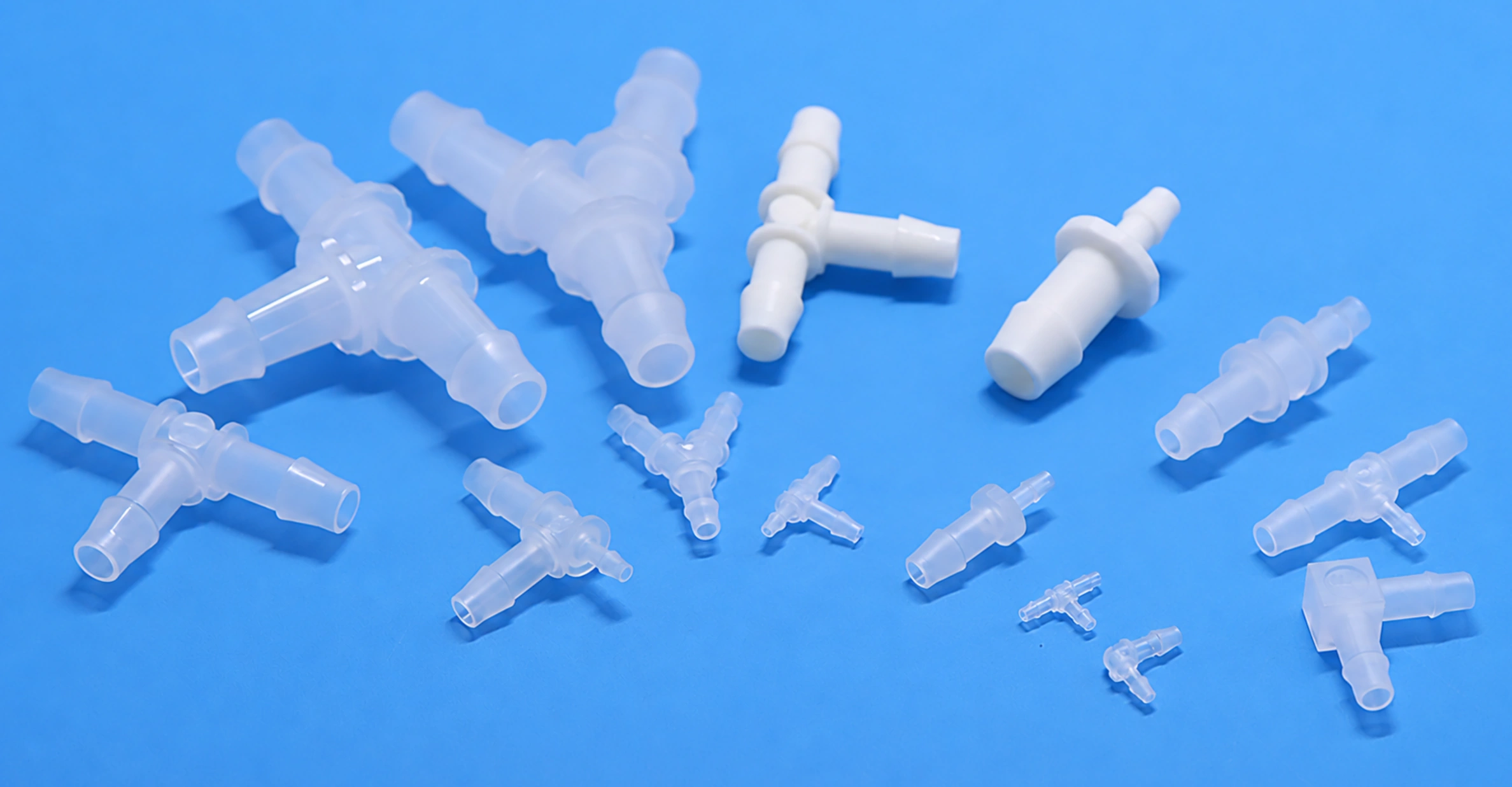
| Series and body | Connection task | Selection focus |
|---|---|---|
| BA straight connector | Join two tubes with the same or different IDs | Equal-size connection or reducing transition; confirm the tubing size at each end |
| BL elbow | Change tubing direction in limited space | Elbow dimensions, outlet orientation and tubing bend clearance |
| BT tee | Create a main path and a side branch | Sizes and positions of all three ports; match branches to the drawing |
| BY wye | Create a Y-shaped split or merge | Branch orientation and all three tubing sizes, considering actual flow direction |
| BX4 cross | Connect tubing in four directions | Port arrangement, assembly clearance and line identification |
| BF4 π-shaped fitting | Create a π-shaped multiport connection | Use the drawing to confirm port positions and equipment clearance |
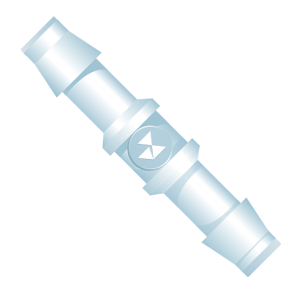
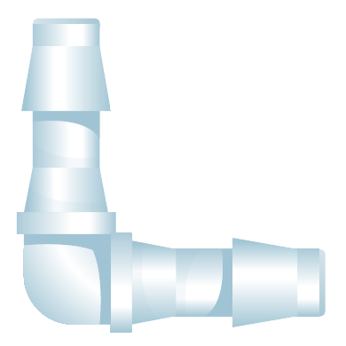
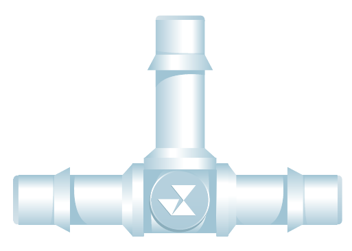
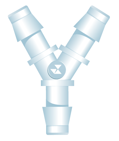
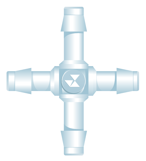
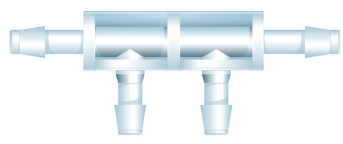
Tees, wyes and multiport bodies provide open flow paths. They do not inherently divide flow equally or prevent backflow. Branch flow also depends on tubing diameter, length, downstream resistance and liquid level. Where backflow prevention or controlled dispensing is required, specify suitable valves or metering components separately.
Equal-size and reducing refer to the compatible tubing ID at each port. BA-32F-PP-N connects two tubes with 3.2 mm IDs, while BA-24F-32F-PP-N transitions between 2.4 mm and 3.2 mm IDs. For reducing tees and wyes, also check which model-code position corresponds to each port; three numbers alone do not establish branch orientation.
BBL barbed plugs close tube ends and should not be confused with through-flow fittings. Thread-to-barb, bulkhead barbed and Luer-to-barb fittings perform additional interface tasks. Their barbed ends still require tubing matching, but thread sealing, panel mounting or male/female Luer compatibility must also be checked separately.
View barbed fitting models; View thread-to-barb fittings; Understand Luer and barbed-end connections
03What do C, F, D, V and X mean, and how should expansion be interpreted?
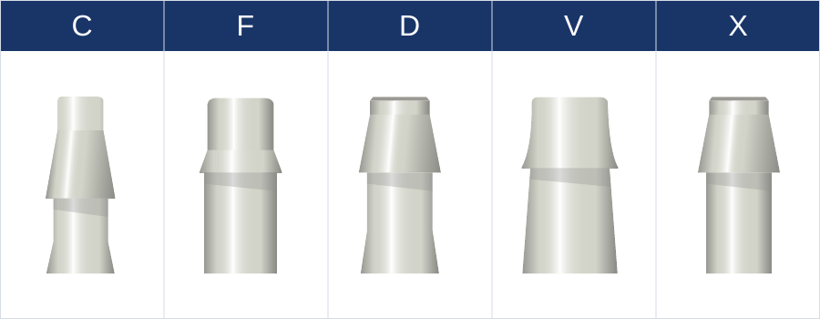
C/F/D/V/X are barb-profile codes following the size code. They are distinct from BA, BL, BT and BY body series. The former describe the surface profile contacting the tube; the latter describe the fluid-path geometry. A straight connector and an elbow can use the same barb-profile code.
| Barb code | Expansion range | Series identifier |
|---|---|---|
| C | 42%–69% | Classic series |
| F | 25%–32% | 400 series |
| D | 24%–50% | 200 series |
| V | 32%–60% | 500 series |
| X | 32%–50% | 600 series |
These ranges compare the tubing expansion associated with the profiles. They are not the tubing material's elongation at break or an allowable expansion during operation. The ranges overlap and cannot establish universal sealing, pressure or pull-off ratings. Evaluate each model with the actual tubing dimensions and material.
A dimensional example of expansion
Comparing the barb crest diameter with the unassembled tubing ID gives a geometric ratio for the expansion needed during insertion. This describes diameter relationships only; it does not calculate insertion force, sealing contact pressure or long-term retention force.
Geometric expansion ratio = (barb crest OD − initial tubing ID) ÷ initial tubing ID × 100%
Use the same units for both diameters, the specific model drawing and actual tubing dimensions.
For BA-32F, the compatible tubing ID is 3.2 mm and the drawing shows a barb crest diameter A of 4.0 mm. Using nominal dimensions, (4.0 − 3.2) ÷ 3.2 × 100% = 25%. This 25% is a geometric example, not a test result for a particular tube. Nor should the minimum and maximum of a profile range be assigned to every model using that code.
For a given tube, greater expansion generally changes insertion resistance and local deformation, but a larger value does not necessarily improve the connection. Compare candidate profiles using the same tubing specification, recording assembly condition, leakage and pull-off behavior before selecting the combination.
04Reading the model code: tubing ID, barb profile and material
| Complete model example | Code interpretation | Connection task |
|---|---|---|
| BA-32F-PP-N | BA straight; 32 = 3.2 mm tubing ID; F profile; PP; N = natural color | Join two tubes with 3.2 mm IDs |
| BA-24F-32F-PP-N | 2.4 mm / 3.2 mm tubing IDs; F profile at both ends | Transition between different tubing IDs |
| BL-32F-PP-N | BL elbow; 3.2 mm tubing ID; F profile; natural PP | Connect tubing around a corner |
| BT-32D-PP-N | BT tee; equal 3.2 mm tubing IDs; D profile; natural PP | Create a three-port branch |
| BY-32D-PP-N | BY wye; equal 3.2 mm tubing IDs; D profile; natural PP | Create a Y-shaped flow path |
Equal-size models omit repeated tubing-end codes. For example, BL-32D-32D-PP-N may be shortened to BL-32D-PP-N. Use the relevant product table for each body's naming convention rather than mechanically adding letters or port counts. PA denotes nylon and W denotes white. Color identifies the model configuration, not a quality grade.
3.2 mm tubing ID is different from 3.2 mm tubing OD
Because a barb enters the tube, match tubing ID first. OD then helps determine wall thickness, routing space and external clamps. A tube with a 3.2 mm ID and 6.4 mm OD has a nominal wall thickness of (6.4 − 3.2) ÷ 2 = 1.6 mm. Its 6.4 mm OD does not make it suitable for a barb intended for 6.4 mm ID tubing.
Compatible tubing ID is also different from the fitting's internal bore. The BA-32F drawing gives bore B as 2.4 mm and overall length D as 23.0 mm: 3.2 mm identifies the tubing, while 2.4 mm is the stated bore. Where flow resistance or particle passage matters, check the actual flow passage instead of treating tubing ID as the minimum diameter throughout the circuit.
BA-32F-PP-N product and drawing; BA-24F-32F-PP-N reducing model; BL-32F-PP-N elbow model
05How should tubing and PP or PA fitting materials be selected?
A barbed connection requires the tube to expand appropriately during insertion and remain wrapped around the stem afterward. Two tubes with the same ID can fit differently if material, hardness, wall thickness or dimensional tolerances differ. Names such as silicone, PVC or TPU alone do not establish compatibility. Another manufacturer's recommended hardness must not become a universal requirement for all FOREACH barbs.
PP and PA are the main FOREACH barbed fitting options; available material combinations vary by model. Check both fitting and tubing compatibility with the actual fluid, concentration, temperature, contact duration and cleaning agent. Confirming fitting resistance alone, without assessing tubing swelling, hardening or changes in recovery, can leave connection problems unresolved.
For rigid tubing that cannot readily expand, evaluate a connection designed for that tubing. Where frequent disconnection is needed, consider a dedicated detachable interface. Repeatedly forcing a tube on and off a barb alters its end condition; successful initial assembly does not establish unlimited reuse.
Material compatibility reference; Rigid tubing fitting selection guide
06Quality evidence for instrument fittings: certification, materials and traceable supply
Equipment manufacturers purchasing barbed fittings should consider downtime, rework, reagent loss and maintenance costs alongside unit price. Compare performance under the same tubing and operating conditions, and whether the supplier provides clear specifications, material information and quality documents. Similar appearance or different prices alone do not determine suitability for an instrument.
Quality management systems support supplier review and production introduction
FOREACH has obtained ISO 9001 and ISO 13485 quality management system certification. The stated scope covers design, development, production and service of fluid-control components and accessories for medical equipment. Equipment manufacturers can use these documents to assess the supplier's quality management foundation alongside drawings, inspection requirements and delivery documentation.
System certification applies to the organization and its certified scope. It does not mean every barbed fitting is certified as a medical device, nor does it replace validation for a particular fluid, pressure, biocompatibility or sterilization process. Projects requiring these properties need evidence for the relevant material or product.
What information do REACH, RoHS and MSDS documents provide?
| Document type | Main purpose | What to check |
|---|---|---|
| ISO 9001 / ISO 13485 certificates | Quality management system and supplier assessment | Certified entity, scope, validity period and current certificate status |
| REACH documentation | Chemical-substance compliance information within the declared or tested scope | Relevant material or product, substance list, revision and date |
| RoHS documentation | Support restricted-substance checks for equipment projects | Sample description, test items, applicable models and declaration scope |
| MSDS / SDS | Material safety information and handling/storage guidance | Material identity, supplier and revision; not product-performance certification |
Each document has a specific role. RoHS or REACH information alone does not establish suitability for long-term contact with a reagent, and an MSDS does not prove leak-free operation. Review material documents alongside operating-condition tests to establish both documentation completeness and whether the fluid circuit performs as required.
From samples to production: consistency of dimensions, appearance and records
FOREACH's quality system covers incoming material verification, in-process inspection, final inspection and delivery records, supported by capabilities such as optical dimensional measurement. For barbed fittings, agreed acceptance requirements can include barb profile, critical dimensions, open flow passages, burrs or surface damage, and model/material identification. Sampling levels, test items and supplied documents should follow the project's quality agreement.
Retain sample approval records, drawing revisions and validated tubing specifications when moving into production. Assess the need for revalidation after tubing or fitting material changes. These records help trace changes in assembly feel or operation to model, material, revision and delivery history, rather than relying on appearance to find a similar replacement.
FOREACH quality systems, certification and inspection capabilities; Download the fittings and tubing catalog (English)
07Selection example: connecting two tubes in an instrument wash line
Suppose a wash circuit needs to join two tubes with 3.2 mm IDs at a fixed connection inside an instrument. BA-32F-PP-N and BA-32D-PP-N are initial structural candidates. Both suit the same nominal tubing ID, but their barb profiles differ; final selection requires comparison with the actual tubing.
- Confirm layout: consider BA for a straight connection, or BL when a change of direction is required. Allow space for the fitting and tubing bend.
- Specify tubing: record ID, OD, tolerances, material, hardness and supplier specification rather than simply requesting “3.2 tubing.”
- Check materials: evaluate PP or another available material against the wash fluid and cleaning agent, concentration, temperature and exposure cycle.
- Check interfaces: confirm both barb codes, drawing dimensions, insertion position and minimum bore so a correct tubing fit does not conceal excessive flow resistance.
- Validate samples: assess assembly, sealing, tensile loading and actual start/stop conditions. Include air-ingress checks under vacuum on suction sections.
- Define supply requirements: include the full model, tubing specification, drawing revision and required material/quality documents in purchasing and acceptance records.
If one tube has a 2.4 mm ID, evaluate BA-24F-32F-PP-N instead of forcing the smaller tube over a larger barb. This is an example selection process, not evidence that these combinations have been validated in a particular instrument.
08How are barbed fittings installed, and when is external clamping needed?
- Inspect model and surfaces. Confirm each tubing size and barb code; check the bore, lead-in and crest for debris, burrs, cracks or scratches.
- Prepare square tube ends. Remove cutting debris and avoid reinstalling old ends that are crushed, cracked or visibly stretched.
- Insert axially. Push the tube to the specified position so it passes the barb and forms the intended fit. Check dimensions and materials before overcoming unusual resistance.
- Provide support and bend clearance. Avoid a sharp bend or sustained tension at the fitting outlet, especially where branches are numerous or tubing is heavy.
- Leak-test under actual conditions. Cover specified pressure, temperature and start/stop cycles; check suction connections for air ingress and record samples and test conditions.
The need for an external clamp depends on the tubing, barb fit, pressure changes, tensile loads and vibration. Match the clamp to the assembled tube OD and the effective clamping location, avoiding misalignment or excessive compression. A clamp cannot correct an incorrect tubing size, and not every barbed connection can be assumed to operate without one.
Do not use grease, solvents or heating to overcome difficult insertion without confirming suitability; these treatments may alter materials or contaminate the fluid path. Stop and depressurize before disassembly, inspect the fitting and tube end after servicing, and repeat the necessary connection checks.
09What should be checked for difficult insertion, leaks, air ingress or pull-off?
| Symptom | Priority checks | Action and verification |
|---|---|---|
| Tube is difficult to insert | OD mistaken for ID; incompatible material, wall thickness or profile | Check both specifications and tube-end damage, then compare compatible combinations |
| Slow leakage after assembly | Insertion position, tube-end cracks, scratched barbs or surface debris | Replace damaged parts, reassemble and retest at specified pressure and temperature |
| Bubbles during suction without visible liquid leakage | Air ingress under vacuum, upstream liquid level and other connections | Check the circuit section by section to distinguish connection leakage from other bubble sources |
| Pull-off during start/stop cycles or under tension | Dimensional fit, tubing softening or relaxation, pressure peaks and external loads | Review operation and routing support, assess clamping and revalidate |
| Different assembly feel after a tubing batch change | Changes in ID, tolerances, hardness or material specification | Compare with approved samples and records; retest connection performance |
| Flow decreases after adding a fitting | Fitting bore, sharp tubing bends, local blockage and total circuit resistance | Check actual flow passages and flow at the point of use, not tubing ID alone |
Define acceptance criteria before testing: allowable leakage, retention requirements and permitted flow variation, with pressure, temperature, fluid, duration and cycling conditions. “Tested without leaking” alone is difficult to reproduce and insufficient for subsequent production acceptance.
10Barbed fitting selection FAQ
Should barbed fittings be selected by tubing ID or OD?
Select the tubing connection size by ID first, then check OD, wall thickness, tolerances, material and hardness. BA-32F-PP-N fits 3.2 mm ID tubing; that does not mean its maximum barb diameter is 3.2 mm. OD helps determine clamping and installation space. When the same tubing ID is paired with different profiles, check drawings and validate insertion, sealing and retention using the actual tubing.
Does a barbed connection always need a clamp?
The need for a clamp depends on the specific barb/tubing fit and operating conditions. Assess tubing material and hardness, temperature, pressure peaks, vibration and external tensile loads, then validate sealing and retention according to the assembly requirements. If required, match the clamp to the assembled tubing OD and effective clamping location without damaging the tube or fitting. A clamp cannot compensate for an incorrect tubing size.
How do I choose both ends of a barbed reducer?
Record the ID, OD and material of each tube, then select the corresponding reducing model. BA-24F-32F-PP-N connects 2.4 mm and 3.2 mm ID tubing. Also check each barb code, drawing dimensions and minimum bore. For reducing tees or wyes, use the drawing to identify which size belongs to each port; the sequence of numbers alone does not establish branch direction.