
What Is a Bulkhead Barbed Fitting? Panel Mounting, Tubing Fit and Model Selection
A bulkhead barbed fitting connects tubing on opposite sides of a panel and fixes the connection to that panel. Also called a bulkhead hose barb, it has barbed ends that enter the tubing and a central mounting section that passes through the panel. A shoulder and nut clamp it in place.
This guide covers FOREACH PMB U28 fittings and PMBSN U28 hex nuts for fixed, infrequently disconnected tubing connections in analytical instruments, IVD and laboratory automation. Check tubing dimensions, materials and mounting space in that order. For frequently replaced external modules, compare a bulkhead quick-disconnect.
01How does a bulkhead barb connect tubing across a panel?
The PMB body has a continuous passage. As tubing is pushed on axially, its wall expands over the barb and contacts the surface to provide sealing and retention. The central shoulder and nut clamp the panel. Tubing sealing, panel retention and the internal passage perform different functions; diagnose each at its own location.
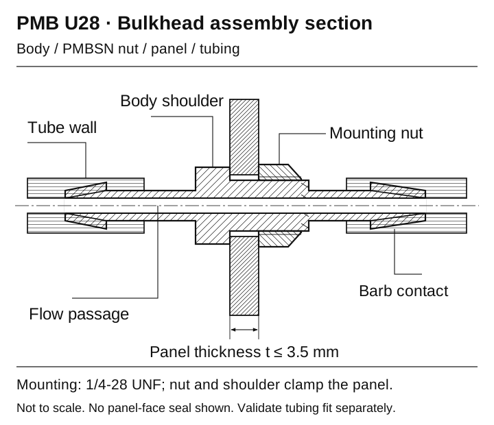
The 1/4-28 UNF thread is for mounting with the PMBSN nut, not for sealing a fluid port. For connection to a manifold, choose a fitting that matches that port's sealing structure.
02When should you choose a bulkhead barb, inline barb, quick-disconnect or luer?
| Connection | Suitable task | Selection focus |
|---|---|---|
| Inline straight hose barb | Join two flexible tubes without mounting the junction to a panel | Tube ID at both ends, tubing material and support |
| PMB bulkhead barb | Fixed panel connection with infrequent tubing removal | Panel thickness, cutout, PMBSN nut and tool space |
| Bulkhead quick-disconnect | Frequently replaced external modules with separation at the mating coupling | Male/female pairing, operating clearance and shutoff after disconnection |
| Bulkhead luer | An external luer component needs a fixed connection point | Mating tapers, locking method and external component interface |
A PMB is disconnected at the tubing end. Repeated removal can deform that end, so inspect stretching, cracks and fit. If automatic shutoff on separation is needed, select a quick-disconnect with the appropriate valve configuration.
For frequent disconnection, read Quick-disconnect pairing and valve configurations; Luer taper sealing and panel mounting.
What Is a Barbed Fitting? Body Types, Tubing Compatibility and Quality Documentation
03Which tube sizes, materials and nuts are available for PMB?
| Tubing ID | Natural PP model | White PA model |
|---|---|---|
| 1.6 mm | PMB-U28-16D-PP-N | PMB-U28-16D-PA-W |
| 2.4 mm | PMB-U28-24D-PP-N | PMB-U28-24D-PA-W |
| 3.2 mm | PMB-U28-32D-PP-N | PMB-U28-32D-PA-W |
For PMB-U28-24D-PP-N, PMB identifies the bulkhead barb series, U28 means 1/4-28 UNF, 24 indicates 2.4 mm tubing ID and PP-N means natural PP; PA-W means white PA. Use the complete model for ordering and matching parts.
Mounting requires a matching PMBSN U28 hex nut: PMBSN-U28-PP-N is natural PP and PMBSN-U28-PA-W is white PA. Nut width across flats is 11.0 mm and thickness is 4.5 mm. List complete body and nut models and quantities in the purchase specification.
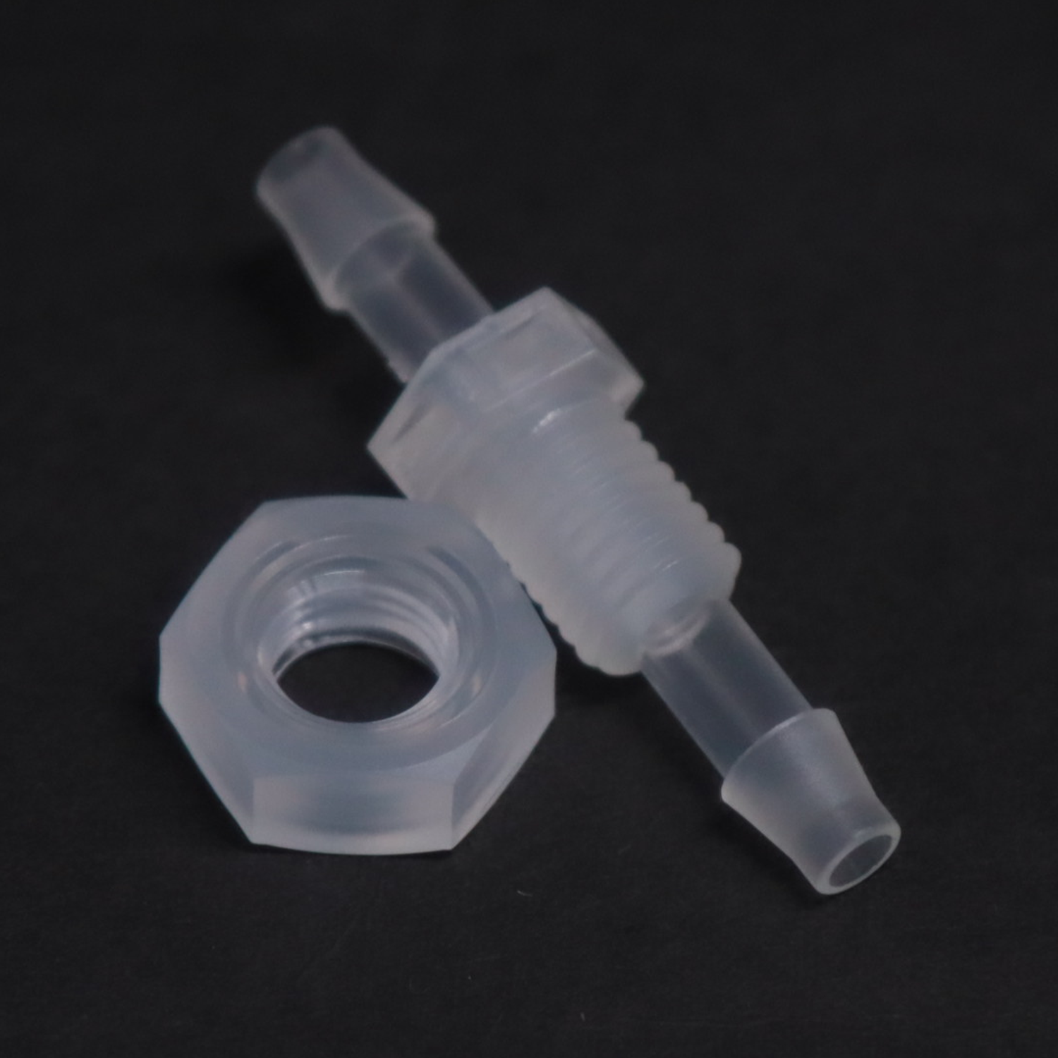
Filter by tubing size and material: View PMB bulkhead barb models.
04How do tubing ID, barb OD and internal bore differ?
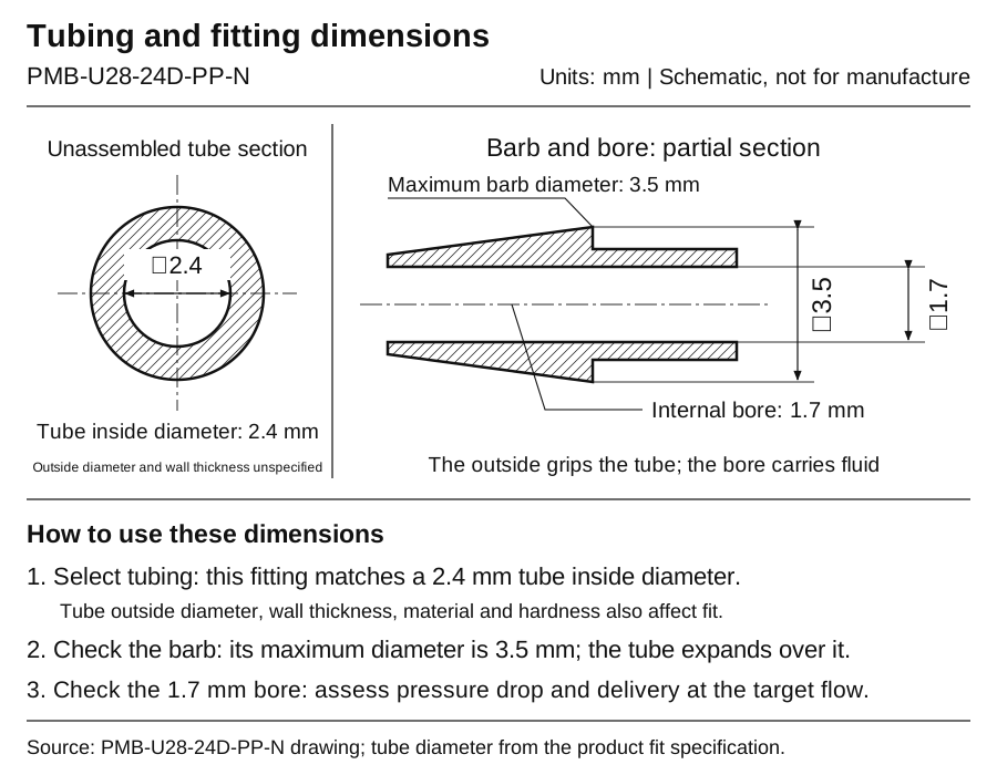
These three dimensions describe the tube, the barb and the flow passage inside the fitting. For PMB-U28-24D-PP-N:
- Compatible tube inside diameter: 2.4 mm. This is the tube opening before assembly; use it to select the tube size.
- Maximum barb outside diameter: 3.5 mm. This is the widest part of the barb; the tube expands over it during insertion.
- Fitting bore diameter: 1.7 mm. This is the fluid passage inside the fitting, used to assess local flow resistance. It differs from the compatible tube inside diameter.
| Base model | Compatible tube inside diameter (mm) | Maximum barb outside diameter (mm) | Fitting bore diameter (mm) | Overall fitting length (mm) | Threaded section length (mm) |
|---|---|---|---|---|---|
| PMB-U28-16D | 1.6 | 2.4 | 1.2 | 21.0 | 6.9 |
| PMB-U28-24D | 2.4 | 3.5 | 1.7 | 25.0 | 8.0 |
| PMB-U28-32D | 3.2 | 4.5 | 2.4 | 31.0 | 8.0 |
Overall fitting length is the distance between the two end faces; use it to plan tubing space on both sides. Threaded section length is the axial length of the external thread, used to check panel and nut assembly space. The body hexagon measures 7.8 mm across flats on all three sizes.
Full dimension drawings (natural PP):
- For 1.6 mm tube inside diameter | PMB-U28-16D-PP-N drawing PDF
- For 2.4 mm tube inside diameter | PMB-U28-24D-PP-N drawing PDF
- For 3.2 mm tube inside diameter | PMB-U28-32D-PP-N drawing PDF
Diameter ratio = maximum barb outside diameter ÷ tube inside diameter
For the size that fits a 2.4 mm tube inside diameter: 3.5 ÷ 2.4 ≈ 1.46. The widest barb diameter is about 1.46 times the tube inside diameter before assembly. This ratio describes fit geometry, not pressure or pull-off capability.
Tube material, wall thickness, hardness and tolerances affect insertion force and contact. Check insertion, sealing and retention under tensile load using the actual tubing. Use the fitting bore diameter to assess local flow resistance and confirm liquid delivery at the target flow rate.
For dimensional fit, read Barb expansion ratio and tubing fit.
05How are the panel hole, thickness and mounting nut specified?
| Mounting item | Requirement | Practical action |
|---|---|---|
| Panel thickness | ≤3.5 mm | Include the panel and any added layers in the clamped thickness; retain adequate nut engagement |
| Cutout | Mounting reference range 6.5–7.5 mm; stated tolerance ±0.1 mm | Before machining, obtain the model-specific panel drawing defining nominal hole size, shape and anti-rotation fit |
| Hole edge and contact faces | Clean and undamaged, without burrs or scratches | Remove burrs that could damage tubing or the fitting; check panel flatness and support |
| Nut tightening | Hand-tight, then a further 1/8–1/2 turn with a wrench | Use an 11 mm wrench for the 11.0 mm flats; control the turn angle and hold the body against rotation |
| Assembly verification | Test the connection under actual operating conditions | Check tubing seals, panel retention and delivered flow separately |
The hole range supports preliminary layout only. Machine the panel from a drawing defining the specific diameter, tolerance and anti-rotation shape. Submit the fitting model and panel drawing for confirmation.
- Check body, nut, tubing and panel drawing. Clean barbs, threads and tube ends; confirm that all components are intact.
- Insert the fitting through the panel with the shoulder seated, fit the nut from the other side and tighten as specified. Check for crossed threads, binding or gaps.
- Push tubing axially until it fully covers the barbed connection length. Support the lines and allow bend and tool clearance.
- Leak-test with the actual fluid, temperature and pressure; verify retention and flow. On the suction side, also check air ingress under vacuum.
Before service, stop the equipment, isolate the line and release residual pressure. Inspect removed tube ends for permanent expansion, cuts or hardening; repair or replace damaged ends before reassembly.
06How should PP and PA bulkhead barbs be selected for the fluid and duty?
| Material | Characteristics and candidate uses | Key checks |
|---|---|---|
| PP | Polypropylene | Low water absorption; generally resistant to many salt solutions, alkalis and weak acids. A candidate for aqueous reagent and rinse lines | Compatibility with oxidizing cleaners, some organic solvents and elevated temperature; deformation and sealing under sustained load |
| PA | Polyamide / nylon | Good mechanical strength, toughness and wear resistance; a candidate where mechanical loading matters | Dimensional and mechanical changes after water absorption; actual PA type/grade and compatibility with process and cleaning fluids |
Natural PP and white PA identify configurations in this series. PA6, PA66 and PA12 differ in water absorption and mechanical behavior, so establish the actual PA type and grade. Select PMBSN nuts for clamping loads and external cleaning exposure; assess tubing using its own material specification.
For a wider material comparison, read Selecting PP, PA and other fitting materials; For listed materials such as PP, see Material compatibility lookup. The current matrix does not include PA.
07How can PMB be selected for an analyzer's panel tubing connection?
Consider 2.4 mm ID tubing on both sides of a 2 mm instrument panel, with a fixed and infrequently disconnected junction. If the process and cleaning fluids suit PP and the chosen tubing, PMB-U28-24D-PP-N plus PMBSN-U28-PP-N is a candidate assembly.
- Tubing: establish OD, material, hardness and tolerance at both ends, then arrange the fit checks described in the dimensions section.
- Mounting: a 2 mm panel is within ≤3.5 mm; also verify the cutout drawing, nut engagement and rear tool access.
- Layout: overall fitting length is 25 mm; add tubing insertion and bend clearances at both ends.
- Flow: the bore is 1.7 mm; check local pressure drop and delivery at the target flow.
- Acceptance: record models, tubing batch, drawing revision, tightening method and leak-test conditions for repeatable assembly.
This example establishes a candidate configuration, not a tested installation in a specific instrument. Recheck affected conditions when tubing, cleaners or service methods change.
For supply, washing and drainage tasks, see Analytical-instrument fluidic applications.
08How should looseness, leakage or tubing pull-off be diagnosed?
| Symptom | Check first | After correction |
|---|---|---|
| Body rocks or rotates | Panel thickness, hole shape, anti-rotation location, nut engagement and tightening | Correct the mounting fit, inspect body and thread damage, and verify retention |
| Seepage at tube/barb interface | Tube size and tolerance, insertion, end damage and material changes | Repair damaged tube ends and retest with actual fluid and operating conditions |
| Tube slips or comes off | Softening, sustained pull, side loads and insufficient retention | Improve support, validate the tubing/fitting pair and assess added retention if necessary |
| More bubbles during suction | Vacuum sealing at tube ends, upstream supply and other air leaks | Isolate sections and retest at actual vacuum and flow |
| Lower flow after installation | Bore restriction, contamination, sharp bends and local resistance | Compare flow and pressure drop before/after installation to locate the restriction |
| Liquid near the panel | Trace tube ends, upstream parts and drip paths to the first wet point | Repair the actual leak, then recheck mounting and nearby connections |
09Bulkhead barb FAQs
Will tightening the panel nut stop a leak at the tubing end?
The PMBSN nut clamps the panel; tubing seals by contacting the barb. Stop and depressurize, then check tube dimensions, insertion, end damage and material changes. Retest after repair. More panel-nut torque cannot correct a poor tube-to-barb fit.
Can this bulkhead barb directly seal a tank-wall penetration?
The PMB described here secures a panel connection and joins flexible tubing. A tank-wall penetration also needs a purpose-designed, validated seal between fitting and wall. Select the complete wall-sealing assembly for the tank structure, fluid and pressure.