
What Are Female Thread Unions? Selecting Straight, Tee, Y and Bulkhead Connections
Female thread unions and connectors are fluid-path components with two or three female threaded ports. Compatible male fittings and sealing assemblies connect flexible or rigid tubing to join, split or combine lines. Bulkhead versions also secure the connection to an instrument panel.
The FOREACH range includes U standard unions, US square-body unions, PMU bulkhead unions, UT tees and UY Y connectors. This guide covers M6×1 and 1/4-28 UNF ports and 0.5–2.0 mm bores. Available dimensions and materials differ by series.
In this range, a union primarily joins fluid lines. Each currently listed website model uses the same thread at all its fluid ports, with M6×1 and 1/4-28 UNF options across the range. Different-thread adapters require a specific model and supply arrangement. A straight, same-thread connection is generally called a union; a conversion between different interfaces is an adapter. Branch and panel-mounted versions are described as tees, Y connectors and bulkhead unions.
01How do female thread unions connect flexible and rigid tubing?
First terminate the tubing with a suitable male fitting, then install it in the female body. Rigid tubing usually needs a nut and ferrule, compression-ring or flanged assembly matched to its outside diameter and port geometry. Flexible tubing can use a compatible threaded hose barb. The complete assembly must both retain the tubing and seal the port.
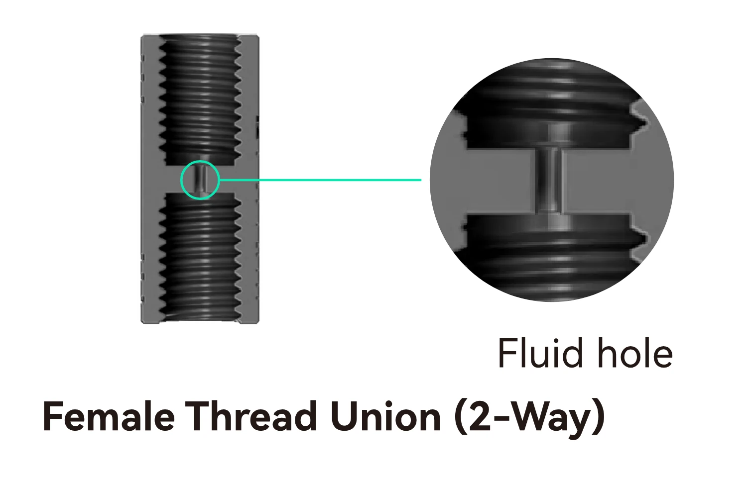
For a matching flat-bottom port and tubing assembly, the thread supplies axial clamping force while the seal forms through correct contact between the sealing component, tube end and port seat. Identical threads alone do not ensure a seal if the seat geometry, port depth or fitting projection differs.
The female body receives a male termination; the tubing must be terminated before installation. Unscrewing a termination and pulling tubing off a barb are separate service operations. Stop and depressurize the system first, then inspect the seals and tube ends. Match replacement parts to the original assembly: similar-looking components may use different sealing structures.
For rigid tube terminations, see Rigid tubing fitting structures and matching components; For flexible tube terminations, see Sealing both ends of threaded hose barb fittings.
02How do U, US, PMU, UT and UY connectors differ?
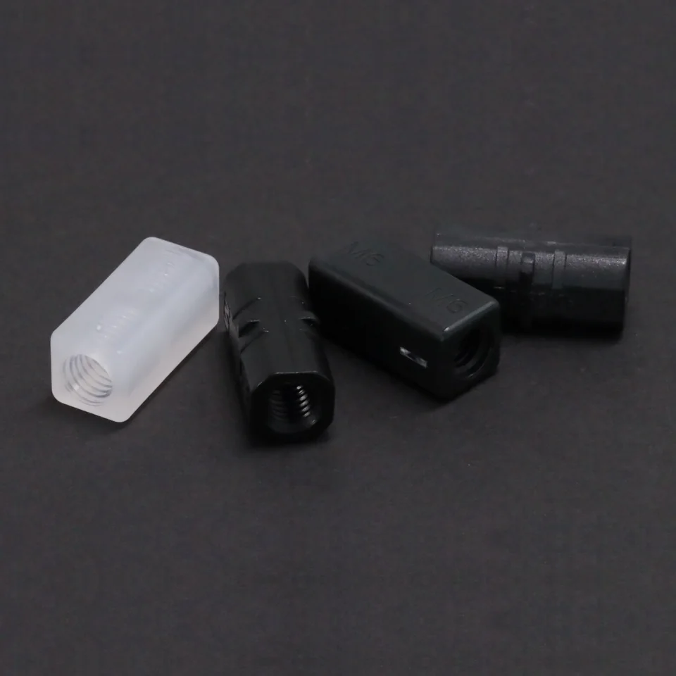
Choose the number of passages and mounting method first. U and US join two lines; PMU adds bulkhead mounting; UT and UY provide three interconnected ports for splitting or combining flow. The square US body differs from the standard U shape, but appearance does not establish bore size or pressure capability.
| Structure and task | Ports and bore | Materials and representative models |
|---|---|---|
| U standard union: join two tubing lines | M6×1 or 1/4-28 UNF; the examples below have a 2.0 mm bore | U-M6-20-AC-B: POM; U-U28-20-PP-N: PP |
| US square-body union: straight connection | M6×1; 0.5, 1.0 or 1.5 mm bore | PP or POM; for example US-M6-10-PP-N, 1.0 mm bore |
| PMU bulkhead union: secure to an instrument panel | 1/4-28 UNF fluid ports; 2.0 mm bore | PP; PMU-M12-U28-20-PP-N |
| UT tee: straight main line and side branch | 1/4-28 UNF; 1.5 or 2.0 mm bore | PP or PPS; for example UT-U28-15-PP-N, 1.5 mm bore |
| UY Y connector: angled branching or merging | 1/4-28 UNF; 1.0, 1.5 or 2.0 mm bore | PP; for example UY-U28-15-PP-N, 1.5 mm bore |
Model codes help identify configurations. In UT-U28-15-PS-B, UT means tee, U28 means 1/4-28 UNF, 15 indicates a 1.5 mm bore, PS denotes PPS in this catalogue, and B means black. AC denotes POM and N means natural. The PS material code here does not mean polystyrene.
Select materials for the body, seals and tubing together. Depending on the model, bodies are PP, POM or PPS. Suitability depends on the fluid, concentration, temperature, contact time and cleaners. Verify the full model and material documentation; color is only an identification aid. The allowable pressure of the complete connection depends on the body, seals, tubing and operating temperature.
For fluid compatibility, read Selecting fitting body and seal materials.
03How should M6×1 and 1/4-28 UNF ports and seals be matched?
M6×1 and 1/4-28 UNF are different threads and must not be screwed together. M6×1 has a 6 mm nominal diameter and 1 mm pitch; 1/4-28 UNF has a 1/4-inch nominal diameter and 28 threads per inch. Similar diameters do not establish compatibility. Forcing a mismatch can damage plastic threads or tilt the fitting.
| Item | What to verify | Why it matters |
|---|---|---|
| Port thread | Complete thread specification, male/female form and mating port; M6×1 and 1/4-28 UNF are parallel threads | M6 or 1/4 alone can omit the pitch or standard; force cannot correct a mismatch |
| Sealing location | Flat-bottom or other seat, port depth, fitting nose length and specified sealing assembly | A tightened thread does not prove the sealing component is correctly seated |
| Tubing termination | Tube ID, OD and material; the specified ferrule, compression-ring or flanged assembly | OD selects the retaining/sealing components; ID affects passage alignment |
| Second or third port | Record every port's specification and matching components | Checking one port does not establish that all ports are compatible |
Both ends of U-M6-20-PP-N are M6×1; both ends of U-U28-20-PP-N are 1/4-28 UNF. Each currently listed U, US, UT, UY or PMU website model uses the same thread at all fluid ports, but tubing and terminations still need separate selection. For different-thread ends, provide both thread specifications, tubing dimensions and fluid to FOREACH to establish the model, availability and mating components.
Body markings help identify ports: M indicates M6×1 and E indicates 1/4-28 UNF. Confirm against the full model and port documentation. Flat-bottom assemblies seal through correct contact between the sealing components and port seat. If the face seal leaks, inspect tube seating, sealing components and the port. Use thread tape or other auxiliary sealing materials only when the assembly instructions specify them.
04How does bore size relate to tubing size and retained volume?
Bore size describes the internal fluid passage; thread size describes the mechanical port interface. They are separate parameters. US-M6 models, for example, share M6×1 ports but offer 0.5, 1.0 and 1.5 mm bores. Changing the bore may leave the mating thread unchanged while changing the transition to the tube ID.
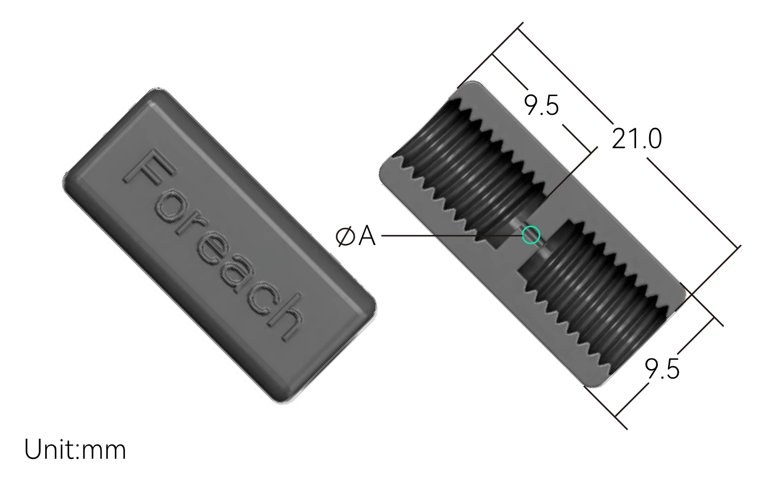
Start with tube ID and target flow, then check whether the fitting becomes a local restriction. Under comparable conditions, a smaller passage may increase pressure drop, while a larger cavity may increase the volume that must be flushed. Passage length, bends, termination geometry, viscosity and operating flow also matter. Bore size alone cannot guarantee flow or carryover performance.
Matching the tube ID to the fitting bore and seating the tube correctly helps reduce steps and stagnant spaces at the connection. These are important conditions for low-retention assemblies. System carryover also depends on internal volume, insufficiently flushed areas and operating sequence, so evaluate it with an actual displacement test.
For reagent switching, sample transfer and wash circuits, test flushing after installation. Use the actual tube lengths, connectors and operating flow, and a permissible tracer or concentration measurement to record the flushing volume needed to restore the outlet to its target condition. Assess this together with leaks, pressure drop and bubbles when deciding whether the bore suits the fluid path.
05How are female threaded tees and Y connectors used to split or combine flow?
UT and UY have three interconnected ports, so either can split one stream into two or merge two streams. A tee suits a straight main line with a side branch; a Y connector provides angled branches. Check tubing direction, bend clearance and mounting-hole positions before comparing bore sizes and operating conditions.
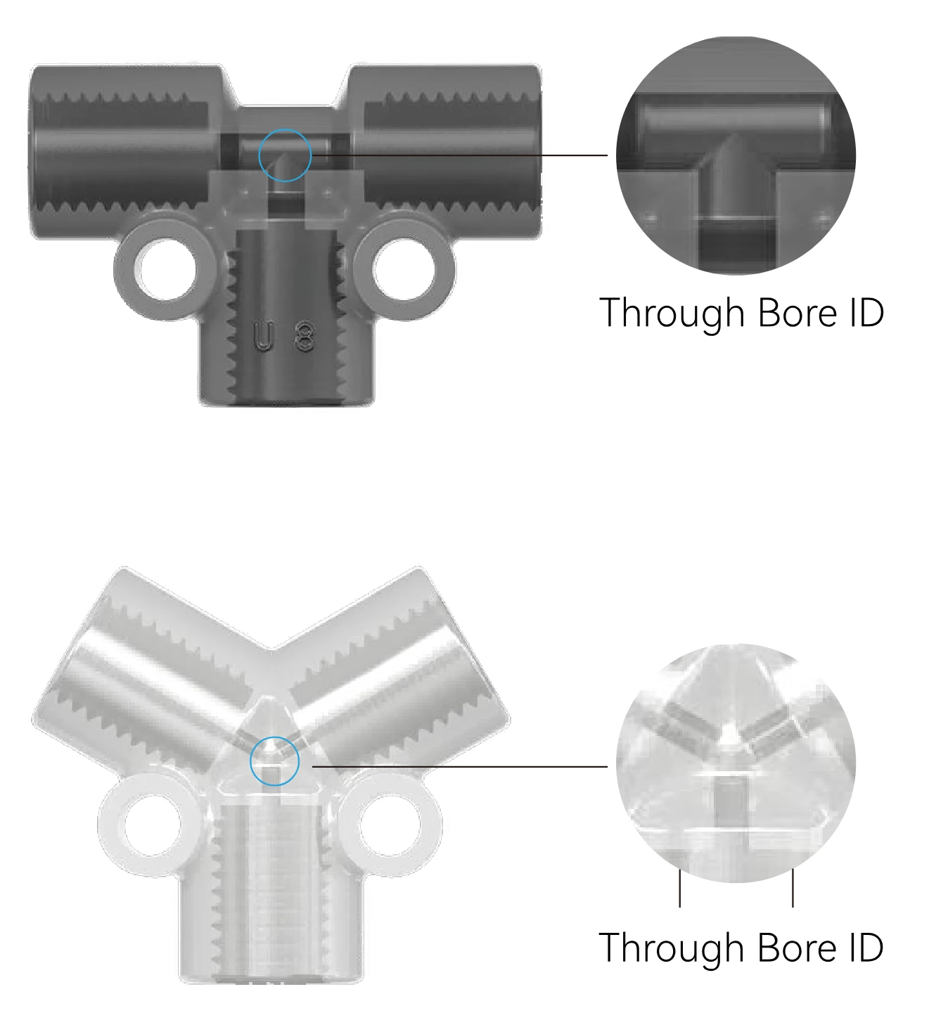
A passive three-port connector does not regulate the flow split. Even equal tube diameters can produce different flows when lengths, downstream backpressures, valve openings or local resistances differ. Equal delivery needs suitable flow control or metering, verified with both branches operating and with each branch operating alone.
Combining streams does not establish complete mixing. Homogeneity also depends on flow ratio, fluid properties and the downstream passage. Neither a T nor a Y shape guarantees it. When one branch is idle, check for backflow caused by pressure in another branch; use appropriate valves or other isolation measures where required.
UT and UY mounting holes allow the branch node to be supported so tubing weight does not continuously load the ports. Leave tool access for tightening, removal and cleaning. Any T-versus-Y pressure-drop comparison must use the actual flow, passage geometry and fluid properties.
06How is a PMU bulkhead union mounted, and which thread serves which function?
PMU-M12-U28-20-PP-N separates mounting from fluid connection. Its external M12×1.5 thread receives the mounting nut; the two female fluid ports are 1/4-28 UNF and the bore is 2.0 mm. M12 in the model does not describe the fluid ports.
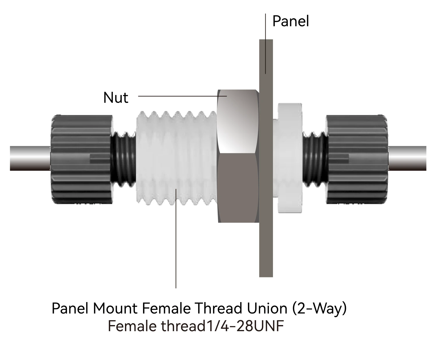
This PMU model accepts a panel no thicker than 12.5 mm and requires a matching nut. Confirm orientation, cutout and clamped thickness before securing the panel between the shoulder and nut. The 12.5 mm value is panel thickness, not hole diameter or insertion depth of a fluid fitting.
- Before assembly, verify the full PMU model, matching nut and panel drawing. Inspect threads, shoulder and cutout edges; remove burrs and debris.
- Pass the body through the panel and secure it with the matching nut. Hold the body against rotation so connected tubing is not twisted.
- Fit each side with a termination compatible with the 1/4-28 UNF port and sealing seat. Treat panel clamping and fluid sealing as separate tightening requirements.
- Provide clearance on both sides for terminations, nut tools and tubing bends, with suitable tube supports.
- Check sealing and flow at the intended temperature, pressure and flow rate. Add an air-ingress check under vacuum for suction-side use.
Choose PMU for nut-secured bulkhead mounting; U standard unions join tubing directly. Other unions with retaining-ring mounts follow their own panel and ring limits, separately from the PMU limit of 12.5 mm.
07How can an analyzer supply two branches from one wash-liquid line?
Consider an analyzer supplying the same wash liquid to two modules through 1.5 mm ID tubing, with a fixed internal branch node. Start with a UT tee or UY Y connector, then complete the port and routing choices. This is a selection example, not a validated customer installation.
- Define operating states: record flow and downstream backpressure for simultaneous and alternating use, including what happens when one branch is closed.
- Select structure and bore: evaluate UT-U28-15-PP-N for a straight main line with side branch, or UY-U28-15-PP-N for angled branches. Both have 1/4-28 UNF ports, 1.5 mm bores and PP bodies.
- Complete all three terminations using actual tube OD, material and port seats. A 1.5 mm tube ID does not specify its OD or identify a ferrule or compression ring.
- Check wash and rinse fluid compatibility with the body, seals and tubing. Route and support the lines around mounting holes and tool clearances.
- Verify flow and isolation: measure branch flow, pressure drop, leaks, bubbles and backflow in each operating combination. Add control if equal delivery is required.
- Record the connector model, all three terminations, tubing dimensions, assembly method and acceptance conditions for procurement and maintenance.
If the line also crosses an instrument panel, assess PMU-M12-U28-20-PP-N separately: its bore is 2.0 mm. Sharing U28 ports with the tee does not make the entire path a uniform bore. Check transitions, displacement volume and mounting space.
For the application context, see Analytical-instrument fluidic applications; For product shapes and interfaces, watch Female thread union introduction video.
08How should leaks, air ingress or reduced flow be diagnosed?
Stop and release residual pressure before locating the fault at a port, tubing termination or body. Do not repeatedly tighten an unverified assembly: mismatched components, an unseated tube, damaged seals and cracked ports require different remedies.
| Symptom | Check first | Remedy and verification |
|---|---|---|
| Port seepage | Thread/seat compatibility, tube seating, scratched or missing seals | Correct the combination or replace damaged parts; tighten as specified and leak-test |
| Bubbles during suction | Vacuum sealing at terminations, upstream supply and other air-entry points | Isolate sections; absence of external drips does not verify vacuum tightness |
| Difficult or tilted engagement | M6/U28 mismatch, pitch, debris and damage | Stop forcing the thread; verify the mating parts and replace damaged ones |
| Reduced or unequal branch flow | Actual bore, blockage, kinked tubing, branch resistance and valve state | Compare segment pressure drops and operating states; a tee is not a flow balancer |
| Residue after cleaning | Tube seating, interface steps, poorly flushed branches and dead ends | Check assembly and flushing paths; measure actual displacement performance |
| Loose bulkhead union or cracked body | Nut retention, tubing twist, lateral loads and fluid exposure | Relieve tubing loads, inspect damage and verify sealing after securing the assembly |
For first assembly, verify the complete body, termination and tubing combination. For maintenance, also inspect seal deformation, wear and tube-end damage. A reusable body does not automatically make seals or preassembled components reusable. Tightening torque and allowable pressure depend on materials, seal design and operating temperature; values from another fitting do not transfer directly.
09Female thread union FAQs
Can these unions convert M6 to 1/4-28 UNF?
Each currently listed U, US, UT, UY and PMU website model has matching fluid-port threads, so these models do not directly convert M6×1 to 1/4-28 UNF. U-M6-20-PP-N has two M6×1 ends; U-U28-20-PP-N has two 1/4-28 UNF ends. For conversion, provide both threads, tubing dimensions and fluid so FOREACH can confirm the specific model and mating components.
Should a leaking female threaded connection be taped or tightened further?
Stop and depressurize first. Check tube seating, sealing components and the port seat. In a flat-bottom face-sealing assembly, thread tape cannot repair a leaking face seal and further tightening may damage the plastic body. Correct the mating parts or replace damaged components, then tighten and leak-test according to the assembly instructions.