
Where sample, reagent and wash-fluid switching occurs in the instrument
Use a port-state table to manage reagent, sample, cleaning and waste destinations. Remove shared-channel residue after switching before the next task; check unintended connections using dead volume, flushing volume and valve-position feedback.
A port-state table should include pump actions, receiving containers and permissible pressure. Shared residue remains after the valve reaches position; the next liquid and assay residue requirements determine whether and how much to flush.
Product responsibilities in this operation
Valves control the current source or destination; the associated drive performs metering or transfer. Port connections, actual positioning and shared-segment renewal must match the operation.
For this operation, confirm: Sample, reagent, wash and waste port states; receiving cuvette; permitted switching pressure; shared liquid inventory; flushing destination and first-dose arrival.
Organize the sequence by actual architecture
- Create a port-state table for sample, reagent, wash fluid and waste, confirming current source, destination and isolated branches in each entry.
- Switch under instrument-permitted pressure and pump states, verify valve position and actual connection, then perform the corresponding aspiration/dispensing action.
- Direct old shared-segment liquid to its specified destination and confirm target-liquid arrival before connecting the reaction cuvette; check unintended connections, leaks and backflow.
Define operating conditions for this task
| To define | Details |
|---|---|
| Actual operating conditions | Sample, reagent, wash and waste port states; receiving cuvette; permitted switching pressure; shared liquid inventory; flushing destination and first-dose arrival |
| Acceptance target | Test each source-to-cuvette route for unintended connections, leakage and backflow. After a source change, measure the liquid needed to clear the shared segment and confirm the first useful dose reaches the intended cuvette. |
| Fault localization | A valve may reach position while old sample, reagent or wash fluid remains downstream. Wrong port mapping, backflow or incomplete replacement can therefore change the next cuvette even when the command completes. |
Further technical reading
Compare product configurations by the roles on this page
| Product | Configuration option | Conditions to verify |
|---|---|---|
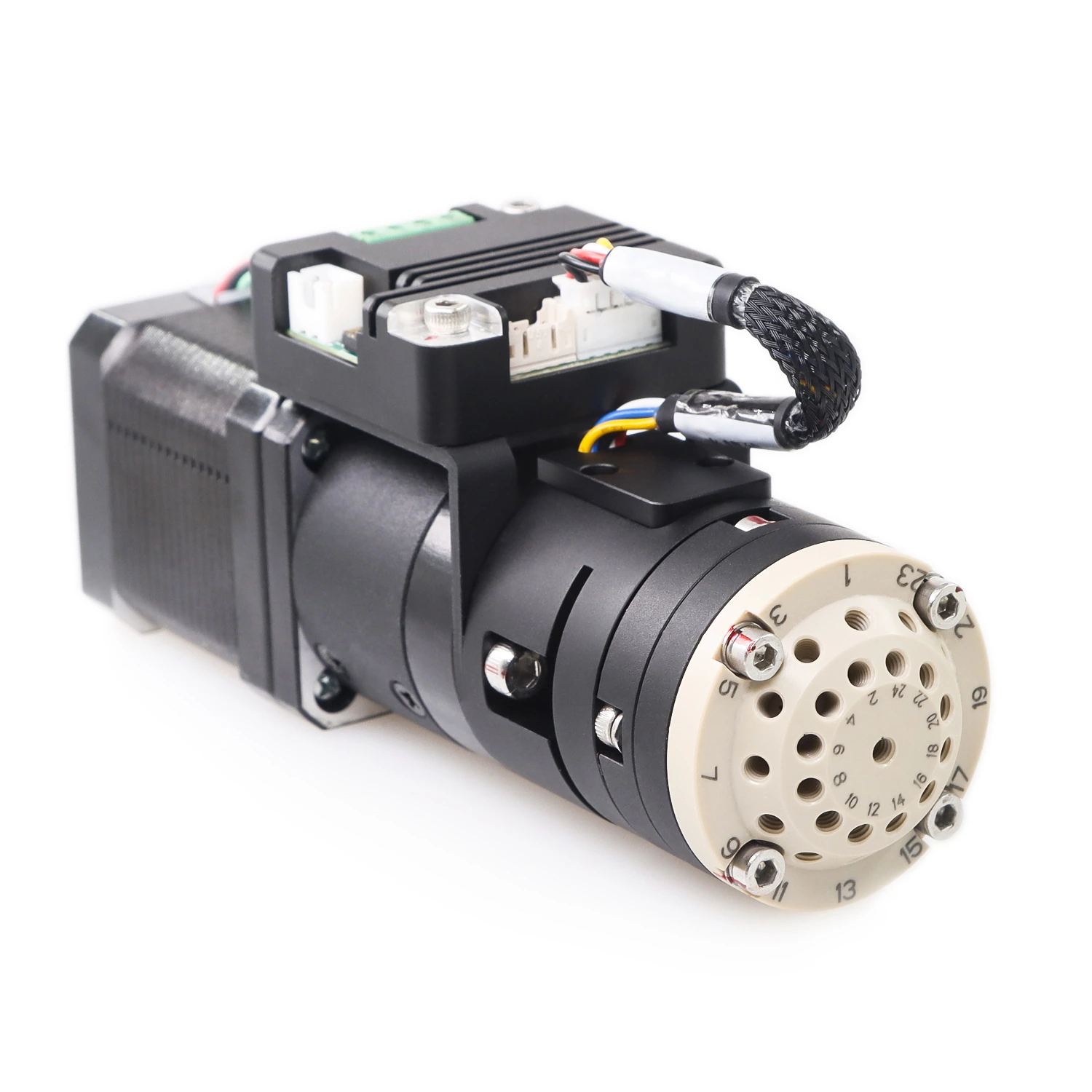
| MRV3 multiport rotary valve | Multiple-source selection | Compare 10-, 16- and 24-port options and port diagrams; verify high-pressure suitability separately |
Validate operation results at the receiver
Test each source-to-cuvette route for unintended connections, leakage and backflow. After a source change, measure the liquid needed to clear the shared segment and confirm the first useful dose reaches the intended cuvette.
Use the next sample or reagent and the assay-relevant blank or high/low sequence to assess residue. Record flushing consumption separately from the volume accepted by the reaction cuvette.
Locate abnormalities and restore the next operation
A valve may reach position while old sample, reagent or wash fluid remains downstream. Wrong port mapping, backflow or incomplete replacement can therefore change the next cuvette even when the command completes.
Suspend the affected route and identify its source, valve state and cuvette. Establish whether any liquid entered that cuvette, route recovery liquid to the specified waste path, and verify replacement and first-dose delivery before resuming.
Valve position establishes a connection state, not sample suitability or an accepted reaction dose. The assay determines how to handle a cuvette with uncertain composition or partial delivery.