
What do these products do in this instrument?
Bubble and pressure sensing: identify air aspiration, bubbles and abnormal pressure
Monitor the actual sample, reagent or wash branch at a location where its state can be interpreted. A sensor upstream of a selector describes the selected supply; it does not independently identify which downstream cuvette received liquid. That association comes from the analyzer sequence and its delivery records.
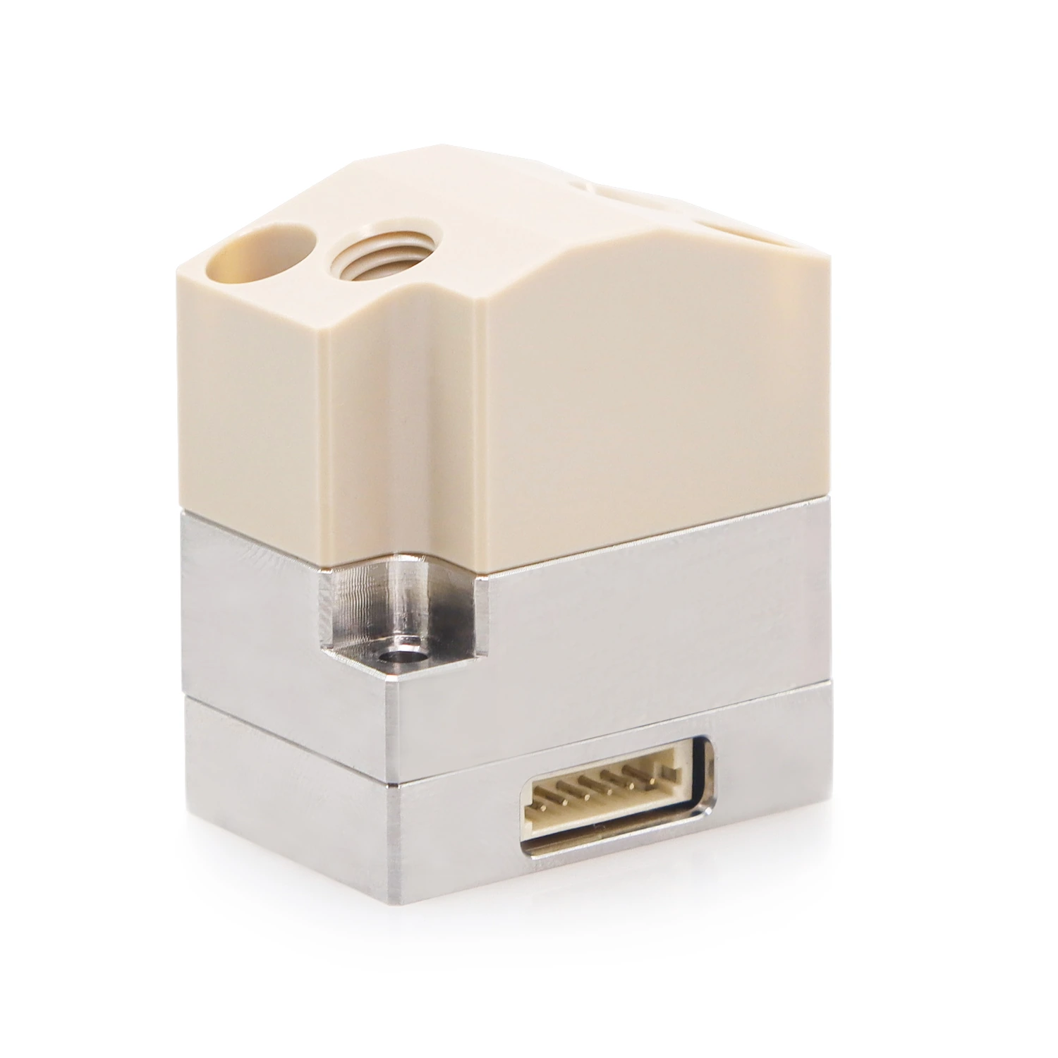
ABD provides bubble or liquid-state signals for defined tubing; PDM5 provides pressure information at a defined location. Configure module, position and action window separately; the controller associates affected samples or tasks.
Choose the branch before choosing the alarm window
For sample aspiration, relate the sensing position to the probe and any intentional air segment. For a reagent supply, decide whether the purpose is to observe bottle depletion before the metering unit or disturbances during delivery. A common supply sensor covers a different part of the path from a sensor on one metering branch; map the intervening valves before assigning an alarm to a sample.
Further technical reading
Keep a fluid-path alarm separate from a confirmed dose
Record the selected source, valve state and cuvette when the event occurs. Distinguish no delivery, partial delivery and a completed transfer using the available observations; mark an unmeasured amount as unknown. The controller can then hold the affected task for the method-defined response. Repeating the command before resolving a partial dose may change the reaction ratio.
Translate actual branch conditions into configuration requirements
| Condition | To confirm |
|---|---|
| Sample aspiration | Specify the actual specimen or justified test medium, probe sequence, intended air segments and sensor position relative to the source and metering unit. |
| Reagent dispensing | Include bottle level, replenishment state and valve transitions in the baseline; compare the first dose after a bottle change with routine delivery. |
| Alarm association | Define which source and cuvette records accompany the signal, how uncertain delivery is represented, and which tasks must remain paused. |
| Operation | Specific operating conditions |
|---|---|
| State monitoring | Sampling or reagent branch, actual liquid and tubing, valve state, intended air segments, acquisition timing and the cuvette affected by a late signal |
State monitoring
During low-volume sample aspiration, compare an alarm with probe position, remaining specimen volume and the actual received sample. Air entry and a restriction can require different handling even when both interrupt the cycle.
During reagent replenishment, keep the source-change event separate from subsequent cuvette additions. Reprime toward the intended outlet and establish which addition was unfinished before resuming the sequence.
Test the complete response while normal valve changes and intended air segments are present. A detector that responds in isolation may still create false stops if the observation window includes an expected transition.
After a fault, verify the repaired path and first subsequent transfer separately from the disposition of the earlier reaction. A recovered sensor baseline does not determine that reaction result.
Compare product configurations by the roles on this page
| Product | Configuration option | Conditions to verify |
|---|---|---|
| ABD bubble-detection module | Bubble or liquid-state identification in defined tubing | Validate detection and false alarms for tubing material, dimensions, medium and action window |
| PDM5 pressure-detection module | Pressure-state monitoring at a defined fluidic location | Confirm range and wetted configuration by model; validate normal baseline and abnormalities separately |

Related operations and architecture comparisons
Sample aspiration and transfer
Low remaining volume, probe contact with a wall and aspiration/dispensing reversals may alter delivery. First measure error in the target container, then assess residue using a blank after a concentrated sample; one calibration cannot address both issues.
Metered reagent dispensing
For repeated dispensing, record usable doses per fill and replenishment points. Confirm restoration of the liquid column after replenishment before evaluating the first dose. Retrying an interrupted action must also avoid duplicate addition to the same cuvette.
Confirm product roles in actual operation
| Operation | Measurements and observations | Priority checks |
|---|---|---|
| State monitoring | Challenge source depletion, a permitted introduced bubble and representative branch-load changes during the relevant phase. Record missed events, false alarms and time from signal to controller action, then measure the affected transfer at the cuvette. | A normal trace after priming may coexist with an earlier incomplete dose. Separate the event that stopped the task from the evidence used to release the next sample. |
Accept the monitoring arrangement only when a recorded event can be traced to the affected operation and a defined response. Check actual first-dose delivery after recovery and assess any carryover through the assay sequence.
Can a common reagent-supply sensor identify a faulty cuvette?
It identifies the state at its sensing location. The controller must relate that event to the selected branch, elapsed transfer sequence and current cuvette; shared volume and delayed signal arrival can widen the set of operations requiring review.
The assay determines sample suitability; full-scale metering specifications cannot replace small-dose and complete-instrument results.