
Where probe/cuvette wash supply and waste removal occur in the instrument
Configure supply and waste removal separately for probe interiors, exteriors and reaction cuvettes. Select wash fluid, contact time, spray location and aspiration height by contamination source, then test carryover with high/low concentration sequences.
Internal-probe, external-probe and cuvette-bottom residue cannot all be solved by increasing the same supply volume. Check cleaning coverage, aspiration height and waste capacity, then validate recovery with high/low concentration switching and blanks.
Product responsibilities in this operation
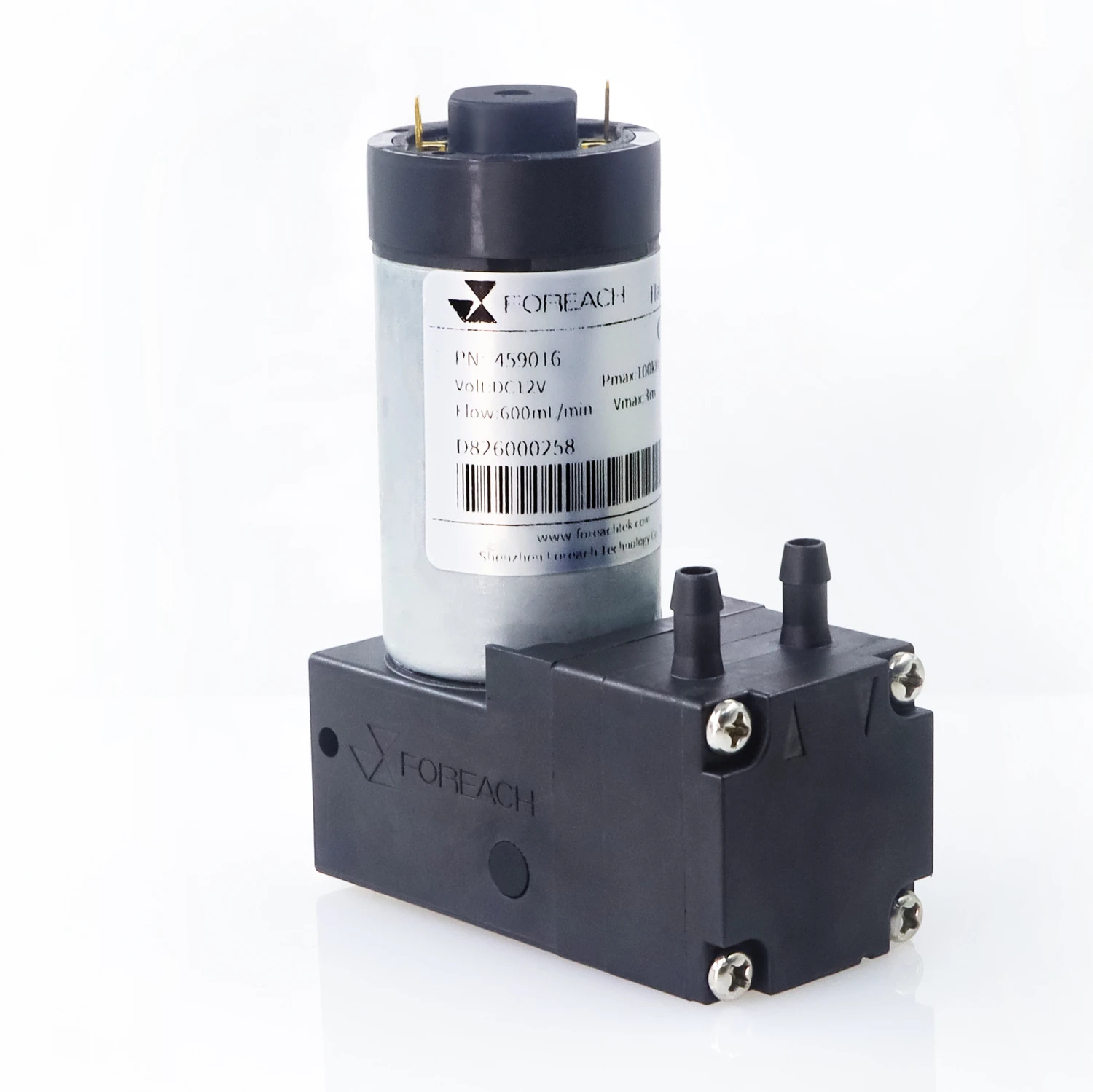
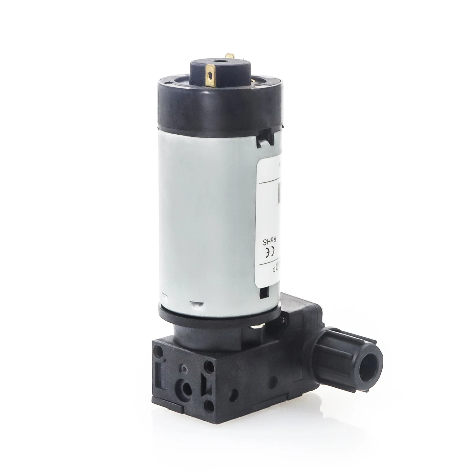
Diaphragm pumps perform suitable liquid supply or aerated aspiration in this task. Confirm inlet phase, branch location and outlet destination separately, then check each branch's operating point.
Compare DPL30, DPL60 and DPL30H by actual supply load. Wash-head, valve, tubing and container resistance jointly determine installed flow; check the supply window and receiving position together.
DPGL800 handles gas or gas–liquid aspiration permitted by its specific configuration. Check inlet gas content, foam, peak inflow and container vacuum; use a separately suitable solution for continuous liquid-only transfer.
For this operation, confirm: Probe-interior, probe-exterior and cuvette surfaces; wash formulation and contact time; supply coverage; aspiration height; peak station inflow and waste-container state.
Organize the sequence by actual architecture
- Mark contaminated surfaces inside and outside probes and in reaction cuvettes separately, confirming each wash fluid, supply inlet, aspiration position and waste destination.
- Start supply according to coverage and contact requirements. Supply pump, wash probe and valves jointly deliver wash fluid; motor runtime alone is insufficient as a record.
- Remove wash fluid through a separate drain branch. Select aspiration/removal configurations for liquid-only or gas-containing inlet conditions, and check peak station accumulation and waste-bottle state.
- Check post-wash residue and the first dose in the next cuvette, then assess carryover and recovery with assay-defined high/low concentration sequences.
Define operating conditions for this task
| To define | Details |
|---|---|
| Actual operating conditions | Probe-interior, probe-exterior and cuvette surfaces; wash formulation and contact time; supply coverage; aspiration height; peak station inflow and waste-container state |
| Acceptance target | Check wash-fluid arrival and contact at the probe interior, exterior and cuvette bottom separately. Under the installed load, measure residual liquid and confirm that drainage handles peak station inflow without pooling. |
| Fault localization | Restricted wash delivery, misplaced aspiration, foam or a full waste vessel can leave different residues at the probe and cuvette. More supply volume alone may increase pooling without cleaning the missed surface. |
Further technical reading
Compare product configurations by the roles on this page
| Product | Configuration option | Conditions to verify |
|---|---|---|
| DPL30 liquid diaphragm pump | Liquid supply or auxiliary circulation | Select by installed resistance, actual wash or working fluid and task window |
| DPL60 liquid diaphragm pump | Liquid supply or auxiliary circulation | Judge by peak demand and installed operating point, not free flow alone |
| DPL30H high-backpressure liquid diaphragm pump | Liquid branches requiring higher backpressure capability | Calculate pressure budget and actual flow first, then confirm interfaces and materials |
| DPGL800 gas–liquid diaphragm pump | Suitable gas–liquid aspiration or container-vacuum branches | Confirm inlet medium and waste architecture; not for continuous liquid-only transfer (100% liquid) |


Validate operation results at the receiver
Check wash-fluid arrival and contact at the probe interior, exterior and cuvette bottom separately. Under the installed load, measure residual liquid and confirm that drainage handles peak station inflow without pooling.
Run the assay-defined high/low concentration sequence and blanks, then examine the first dose through the cleaned path. Distinguish insufficient surface cleaning from residual wash liquid diluting the next addition.
Locate abnormalities and restore the next operation
Restricted wash delivery, misplaced aspiration, foam or a full waste vessel can leave different residues at the probe and cuvette. More supply volume alone may increase pooling without cleaning the missed surface.
Stop supply to a station that cannot drain and identify affected probes and cuvettes. Restore supply coverage and waste removal, complete the applicable wash sequence, and verify residual liquid and carryover before returning that station to sample handling.
Wash-pump flow is only one input to cleaning. Select supply and waste configurations for their actual inlet media, and validate cleanliness and the next reaction with the assay.
References
View references (4)
- [1]FOREACH DPL30 liquid diaphragm pump: configurations and specifications
- [2]FOREACH DPL60 liquid diaphragm pump: configurations and specifications
- [3]FOREACH DPL30H high-backpressure liquid diaphragm pump: configurations and specifications
- [4]FOREACH DPGL800 gas–liquid diaphragm pump: configurations and specifications