
What Is PTFE Tubing? Properties, Limitations and Selection for Instrument Fluidics
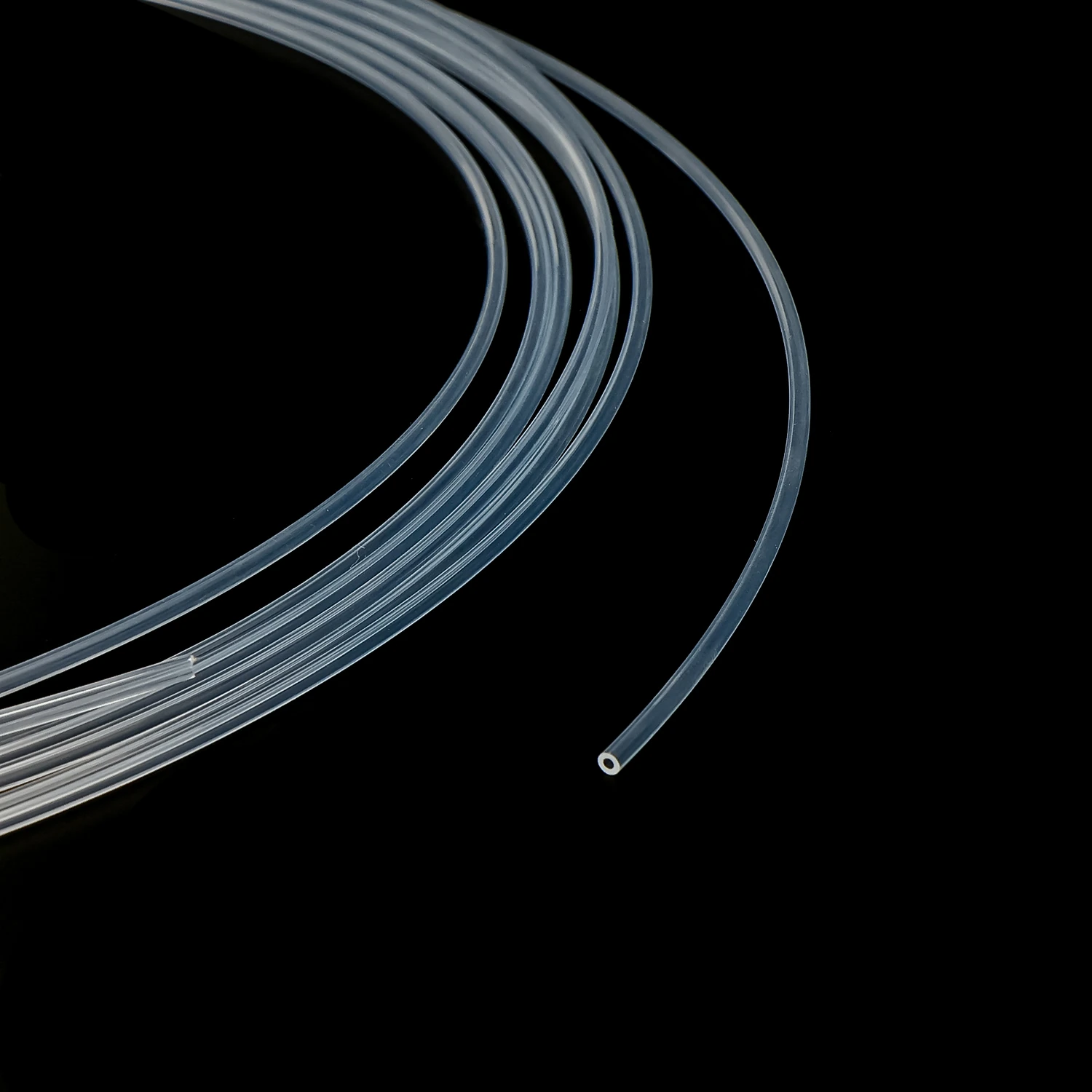
PTFE tubing is made from polytetrafluoroethylene, a fluoropolymer with broad chemical resistance and low surface energy. In analytical instruments and laboratory equipment, small-bore PTFE tubing transfers reagents, wash fluids and solvents between reagent bottles, pumps, valves, sampling probes and other fluidic components.
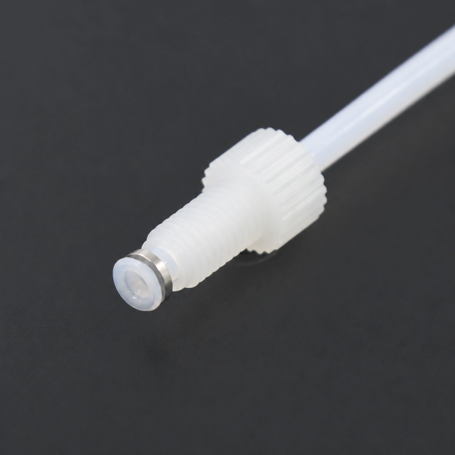
For instrument integration, PTFE tubing is also cut to specified lengths and fitted with flanged, retaining-ring or ferrule connections to form tubing assemblies. Diameter and length affect hydraulic resistance and internal volume, while the end connections must match the instrument ports. Material, dimensions and connection method should therefore be selected together.
01What is PTFE tubing made of, and how is it manufactured?
PTFE stands for polytetrafluoroethylene. Its molecular structure gives it broad chemical resistance and low surface energy. For instrument tubing, specify PTFE material, the exact model, inside and outside diameters, and operating conditions so the material requirement identifies a finished tube.
PTFE retains a very high melt viscosity above its melting point. Small-bore tubing is commonly paste-extruded: fine powder is mixed with a processing aid and preformed, extruded into a tube, then processed to remove the aid and sintered. Sintering bonds the particles into the finished product. Voids in the starting powder do not make ordinary finished tubing equivalent to a porous filter membrane or expanded PTFE.
Resin grade, extrusion and sintering conditions affect dimensions, appearance and permeation. Tubes made from the same polymer can differ in tolerances, transparency, bending behavior and connection performance. Bonding or end forming requires a qualified surface treatment, mechanical connection or dedicated forming process; ordinary thermoplastic melt-assembly methods cannot simply be transferred to PTFE.
02What are the benefits and limitations of PTFE tubing in a fluid path?
| Material or finished-tube characteristic | Value in instrument fluidics | Selection limits |
|---|---|---|
| Broad chemical resistance | A material candidate for many reagents, wash fluids and solvents | Check fluid composition, concentration, temperature and contact time, including fittings and seals |
| Low surface energy and low friction against solids | Can help reduce certain adhesion problems | Does not mean zero adsorption for every sample or directly imply lower liquid pressure drop |
| Broad material temperature range | A candidate where temperature resistance is required | A resin temperature limit is not a shared rating for finished tubing and its connections |
| Creep under sustained load | Usable with suitable gripping and end-connection designs | Sealing stress can change under sustained compression; verify retention and sealing |
| Gas permeation occurs | Evaluate routine transfer against the permitted gas load | For degassed liquids and oxygen-sensitive detection, consider length, wall thickness, temperature and residence time |
| Natural tubing is commonly milky white, translucent to opaque | Select natural or other colors for the application | Verify bubble visibility and light protection with actual samples |
PTFE's low coefficient of friction generally describes contact between solids; it is not an input to liquid flow-resistance calculations. For fully developed laminar flow in a circular tube, pressure drop depends primarily on viscosity, flow rate, length and ID. Sample residue also depends on interfacial adsorption, fitting dead volume, cleaning and residence time. A nonstick description alone cannot guarantee low residue.
03What temperature and pressure can PTFE tubing withstand? Material limits versus assembly ratings
Determine operating temperature together with pressure, fluid and duration. A resin temperature limit is not an assembly temperature rating. Tube-wall behavior under sustained load and the limits of fittings, ferrules and seals jointly define the operating envelope. Check the chosen model's allowable conditions at the actual temperature.
| Check | Required conditions or information | Design criterion |
|---|---|---|
| Continuous and peak pressure | Normal transfer, valve switching and blocked-outlet conditions | All operating states remain within the assembly's allowable range |
| Temperature and duration | Fluid temperature, internal equipment heating, cleaning and hold time | Use allowable conditions at the relevant temperature; do not combine two independent maxima |
| Suction under negative pressure | Actual negative pressure, wall thickness, bend radius and support | Check collapse, kinking and air ingress at fittings; positive-pressure testing alone is insufficient |
| Connections and repeated assembly | Tube OD, tolerance, port geometry, assembly method and reassembly cycles | Confirm sealing, retention and life for the tubing/end-connection combination |
For high-pressure paths such as HPLC, choose tubing and connections with relevant working-pressure data. PEEK or stainless steel may be candidates, but changing to PEEK is not itself pressure validation. ID/OD, temperature, fluid and fittings still need to match.
04Where is PTFE tubing used in instruments? Reagent, wash and waste lines
| Tube segment or task | Reason to consider PTFE | Priority checks |
|---|---|---|
| Supply line from reagent bottle to pumps and valves | Screen chemically resistant tubing for fluid compatibility | Suction resistance, vacuum sealing, liquid level and residence time |
| Wash-fluid and disinfectant connections | Consider both process and cleaning fluids | Maximum concentration, cleaning temperature and tube-end condition after prolonged exposure |
| Low-pressure solvent lines for chromatography or sample preparation | Balance solvent exposure with small-bore routing | Degassing location, gas re-entry and pump suction performance |
| Mixed-waste discharge line | Assess the effects of all waste fluids | Mixture compatibility, deposits, outlet elevation and pressure during blockage |
| Connections between pumps, valves, sampling probes or chips | Size to suit flow and internal-volume requirements | ID, length, port dead volume, fitting geometry and tube-end processing |
These are candidate locations in a fluidic design, not evidence that one PTFE configuration suits every instrument. Microfluidic fittings are often selected by OD, but a tube that fits into a port does not necessarily seal. If a chip accepts only elastomeric tubing, use an interface transition appropriate to that port.
Ordinary PTFE instrument connection tubing should not be used directly in the roller-compressed section of a peristaltic pump. This position requires reliable recovery after repeated compression. Use elastomeric or dedicated composite pump tubing qualified by the pump manufacturer. PVC and silicone also require a suitable pump-tubing grade and operating basis.
05How do you choose between PTFE, PEEK, FEP and PFA tubing? Pressure and visibility requirements
| Selection factor | PTFE tubing | PEEK tubing |
|---|---|---|
| Pressure and dimensions | Confirm for the specified wall thickness, temperature and end connections | Use configurations with explicit high-pressure ratings; do not extend those ratings to every model |
| Fluid | Broad chemical resistance, with limits for particular fluids and conditions | Exclude or specifically assess concentrated sulfuric and nitric acids; THF, DMSO and dichloromethane can cause tubing to swell |
| Mechanical connection | Consider creep and retention under sustained compression | Consider stiffness, bend radius and tube-end interaction with sealing components |
| Temperature | Material temperature resistance does not replace assembly ratings | Also check the temperature/pressure combination for the finished tube and fittings |
| Typical fluidic tasks | Qualified transfer lines for reagents, wash fluids, solvents and waste | Small-bore analytical-instrument connections qualified for their rated conditions |
Where liquid-level or bubble observation is needed, consider more readily viewable tubing such as FEP or PFA and verify actual visibility with the chosen wall thickness, color and lighting. For gas-sensitive work, compare data for the target gas under equivalent geometry, temperature and flow conditions; FEP and PFA are not universally less permeable than PTFE. A material change does not automatically eliminate air ingress at fittings or gas coming out of solution.
06How should PTFE tubing ID and length be selected? Calculate pressure drop and internal volume together
Start with the target flow rate, viscosity, available pressure and tube length, then select ID. The Hagen–Poiseuille relationship estimates distributed pressure drop for steady, incompressible Newtonian fluid in fully developed laminar flow through a rigid circular tube. It excludes fitting losses, entrance effects, pump pulsation and bubbles, and does not directly apply to non-Newtonian fluids or significantly deformed tubing.
ΔP = RQ = 128μLQ / (πd⁴);V = πd²L / 4
ΔP: pressure drop (Pa); R: hydraulic resistance (Pa·s/m³); μ: dynamic viscosity (Pa·s); L: tube length (m); Q: volumetric flow rate (m³/s); d: ID (m); V: geometric internal volume (m³).
Theoretical example: at 1 mPa·s viscosity, 1 m length and 1 mL/min flow, a 0.5 mm ID gives approximately 10.9 kPa distributed pressure drop and 0.196 mL internal volume. Increasing ID to 1.0 mm gives approximately 0.68 kPa and 0.785 mL. A larger ID therefore reduces pressure drop while increasing the liquid volume to be displaced. These are ideal circular-tube calculations, not measurements of FOREACH products.
For a hypothetical tolerance of ±0.025 mm on a 0.5 mm ID, hydraulic resistance varies by about −18% to +23% from nominal at unchanged viscosity and length. This is not a FOREACH tolerance specification; it illustrates why ID tolerance matters. Under constant-pressure drive it affects flow. In a metering-pump system, the operating point, valve timing, tubing compliance and bubbles must also be considered: resistance deviation is not directly equivalent to dispensing error.
07How should fittings be matched to PTFE tubing? Cold flow, OD tolerance and end geometry
Fittings generally match tube OD and its allowable tolerance. ID affects resistance and volume, while OD, wall thickness and material condition affect sealing and grip. A 1/16-inch OD is 1.5875 mm, close to but not equal to 1.6 mm. The same connection is acceptable only if its permitted size range covers the actual tube. Thread engagement alone does not establish compatibility with the port cone, flat bottom or sealing position.
Under sustained compression, PTFE can creep and change tube-end shape and sealing stress over time. More tightening is not necessarily more reliable: excessive compression can constrict the bore, damage the wall or destabilize retention. Follow the fitting instructions for cutting, insertion depth, tightening and support, then verify pressure holding, vacuum sealing and reassembly. Any retightening must follow assembly requirements; routine retightening is not a universal maintenance method.
For fixed-length tubing assemblies, drawings should identify material, ID/OD, overall length and its reference points, both end fittings, threads, tube-end processing and routing. Flanged, retaining-ring and ferrule connections seal differently; a thread specification alone does not define the complete connection.
08Can PTFE tubing contribute to bubbles or residue? Permeation, air leakage and outgassing
Gas can permeate polymer tubing walls. Permeation depends on gas species, partial-pressure difference, temperature, wall thickness and exposed area. Degassed liquid residing in a long tube can reabsorb gas, which may not immediately form visible bubbles. Gas permeation through ordinary finished PTFE is distinct from flow through the interconnected pores of a porous membrane; bubbles alone do not prove holes or liquid leakage in the wall.
Within allowable operating conditions, begin by shortening the suction line and comparing control sections with the same ID and length. Independently check vacuum sealing at fittings, liquid level and temperature changes. If reassembling a fitting changes the bubbles substantially, investigate air ingress there first. If warming or greater suction vacuum produces bubbles, also assess gas coming out of solution. Measure dissolved oxygen directly where it matters rather than relying only on visible bubbles.
Low water absorption and chemical resistance do not mean zero extractables or adsorption. For trace analysis or adsorption-sensitive samples, select resin, color and cleaning conditions, then compare blank fluid, exposed fluid and samples after rinsing. After a color or batch change, recheck method-relevant background and residue. Light protection from black tubing also requires evaluation at the target wavelengths and wall conditions.
09Which FOREACH PTFE tubing specifications are available? Models, colors and packaging
Natural, black and other color configurations are available, with IDs spanning 0.5–4.0 mm and ODs spanning 1.6–6.0 mm across the TH1 and TH2 series. ID/OD and color combinations are model-specific. Black PTFE tubing can be considered for light-sensitive reagent lines; light protection must be assessed for the reagent's sensitive wavelengths. Tubing is available by the roll, and compatible sizes can be made into flanged, retaining-ring or ferrule tubing assemblies. Length, single- or double-ended connections, and A/B fittings can be specified by drawing to reduce on-site processing and assembly.
| Model | ID × OD (mm) | Color | Packaging |
|---|---|---|---|
| TH1-PTFE-N-08-16-100FT | 0.8 × 1.6 | Natural | 100 ft/roll |
| TH1-PTFE-B-08-16-100M | 0.8 × 1.6 | Black | 100 m/roll |
| TH2-PTFE-N-05-16-100M | 0.5 × 1.6 | Natural | 100 m/roll |
| TH2-PTFE-N-40-60-100M | 4 × 6 | Natural | 100 m/roll |
The same ID/OD may be offered in different series, colors or packaging. Keep the complete model, product code and pack unit in orders and BOMs. A 100 ft roll is 30.48 m, not 100 m. A transparent color entry describes that particular model; it does not establish the appearance or bubble-detection capability of all PTFE tubing.
10How should PTFE tubing samples be validated? From dimensions to long-term operation
- Check model, color, batch and packaging; measure ID, OD and length; inspect cuts, bends and surface damage. Apply the confirmed tolerances for that configuration.
- Expose samples to the actual reagent and cleaning fluid, recording concentration, temperature and time. Monitor appearance, dimensions, mass and analytical background.
- Assemble the actual fittings and assess static sealing, dynamic pressure changes and suction vacuum within the confirmed assembly operating limits.
- At the target flow and actual routing, measure pressure drop, delivered volume, displacement time and bubbles; compare with calculations and control tubing where needed.
- After the planned continuous run, temperature cycles and maintenance reassembly, recheck sealing, end deformation, retention and analytical results, and retain traceable acceptance records.
Selection should make material, dimensions and connections work together for the instrument's task. Provide FOREACH with fluid and concentration, ID/OD, length, flow, temperature, working and peak pressure or vacuum, fittings and routing drawings to review model and assembly options. Final suitability should be established by prototype validation under agreed conditions.
11Explore other instrument tubing materials
12PTFE tubing selection FAQ
1. What conditions should be specified when selecting black PTFE tubing for light-sensitive reagents?
Specify the reagent's light-protection requirements, light source and exposure duration, residence time in the tubing, and tube dimensions and wall thickness. Check light protection at fittings and transition sections as well. Black appearance alone does not establish shielding performance; use transmittance data for the selected tube or evaluate reagent stability under actual operating conditions.
2. What information is needed beyond ID and OD to specify a custom PTFE tubing assembly?
Provide tube length, measurement reference points and tolerance; fitting models, threads, sealing geometry and end-processing requirements for ends A and B; and process fluid, cleaning fluid, temperature, flow rate, working pressure and suction vacuum. For restricted spaces or curved routing, include a routing drawing and fixing positions. Thread specifications alone do not define a connection: mating ports and sealing faces must also be identified.