
What Is PFA Tubing? Material Properties, Cleanliness and Instrument Fluidics
PFA tubing is made from perfluoroalkoxy polymer, a fluoropolymer with broad chemical resistance that can be melt-extruded into small-bore tubing. In analytical instruments, it serves reagent transfer, sample preparation and wash lines, connecting reservoirs, pumps, valves and detection-related components.
PFA tubing can also be made into fixed-length assemblies with flanged, retaining-ring or ferrule connections to suit instrument ports and routing. Where background and sample residue matter, consider tubing, fittings and cleaning as one wetted path, and select tube dimensions and assembly configuration for transfer volume and port geometry.
01What is PFA tubing made of, and how does its processing differ from PTFE?
PFA is a perfluoroalkoxy polymer made by copolymerizing tetrafluoroethylene with perfluoroalkyl vinyl ether monomers. It combines the broad chemical resistance of perfluorinated polymers with melt processability and can be extruded into small-bore tubing.
PFA and PTFE are different materials. Small-bore PTFE commonly uses paste extrusion and sintering, whereas PFA can be melt-extruded. These differences affect processing and end-forming methods. Use finished-tube data for actual tolerances, surface quality and mechanical properties.
PFA tubing can appear transparent or translucent. Visibility depends on diameter, wall thickness, color and lighting. Transparency does not establish resin grade, cleanliness or pressure capability and cannot replace material and batch records.
02How should PFA, FEP and PTFE tubing be compared for operating conditions?
| No. | Comparison factor | Selection method |
|---|---|---|
| 1 | Fluid compatibility | List reagents, cleaning fluids and liquids retained during shutdown; screen all three materials by concentration, temperature and contact time |
| 2 | Temperature/pressure combination | Use allowable conditions for the specified tube size and fittings, checking continuous operation and pressure peaks separately |
| 3 | Visibility requirements | Compare liquid-level, color and bubble visibility in actual tube samples, not material names alone |
| 4 | Analytical background | Compare blanks, extractables and adsorption using the same contact liquid, duration and analytical method |
| 5 | Assembly and maintenance | Compare port fit, tube-end processing, bend radius and sealing after reassembly |
FEP and PFA are both melt-processable, but PTFE, FEP and PFA all require finished-product specifications. For elevated-temperature use, first review tubing and connection ratings at that temperature. For liquid observation, compare actual samples. A claim that PFA is a superior material does not replace these checks.
Even the same material can differ in hydraulic resistance, permeation and sealing because of wall thickness, length and fittings. If existing FEP or PTFE meets fluid, analytical and life requirements, define what a change to PFA is intended to improve and verify that metric under equivalent conditions.
03How is PFA tubing cleanliness evaluated?
Chemical resistance describes suitability for a fluid; cleanliness depends on resin, extrusion, cleaning, packaging and contact during assembly. The material name PFA is not proof of high purity, zero extractables or low analytical background. For trace analysis, express cleanliness as measurable acceptance criteria.
- Define target metrics: depending on the analytical method, consider metal or organic background, particles, analyte adsorption or carryover.
- Establish blanks: compare the original reagent blank, liquid after tube contact, and the system blank after contact with fittings, pumps, valves and the complete fluid path.
- Control exposure: record fluid composition, concentration, temperature, time and contact area. Results under different conditions cannot directly rank materials.
- Verify cleaning and recovery: use the instrument's cleaning procedure to assess rinse volume, recovery time and residue in the next sample.
- Control batches and assembly: retain material, tubing-batch, cleaning and packaging records, and manage contamination during cutting and fitting installation.
PFA can be screened as a wetted material for trace-element analysis, but the complete fluid path determines the blank. Replacing only the tube while retaining unsuitable fittings, cleaning fluids or containers does not resolve system background.
04Which instrument fluidic tasks use PFA tubing?
| Fluidic task | PFA selection focus | Installation checks |
|---|---|---|
| Reagent supply in analytical instruments | Fluid compatibility, small-bore transfer and port fit | Suction resistance, bubbles and vacuum sealing at fittings |
| Sample-preparation connections | Suitability for exposure to both sample and cleaning fluid | Blanks, adsorption, displacement and carryover |
| Wetted sections for trace analysis | Material and cleanliness requirements of the analytical method | Material, connection and system blanks |
| Wash or rinse lines | Cleaning agent, temperature and cycle count | Changes in dimensions, sealing and background after treatment |
These tasks require configurations selected for their specific conditions; they are not universal application claims for a model. In systems with peristaltic pumps, distinguish the repeatedly compressed pump-head section from connections before and after the pump. Ordinary small-bore PFA tubing cannot be used directly as roller-compressed pump tubing.
For light-sensitive reagents, design shielding for the target wavelengths, exposure time and exposed routing. Transparent tubing supports observation but is not a shielding measure. For degassed liquids, minimize unnecessary exposed length and check fitting air ingress and changes in dissolved gas.
05How are PFA tubing ID, OD, wall thickness and length selected?
Choose ID for both flow and retained volume, and OD for both fitting compatibility and wall thickness. At fixed OD, increasing ID reduces the wall thickness. Equal OD therefore does not establish equal pressure capability or end-processing conditions.
Wall thickness t = (D − d) / 2; internal volume V = πd²L / 4
D: OD; d: ID; L: length. Internal volume is a geometric value. Actual cleaning displacement also depends on mixing, connection dead volume and the cleaning procedure.
For a geometric comparison at 1.6 mm OD, IDs of 0.5 mm and 1.0 mm give wall thicknesses of 0.55 mm and 0.30 mm. At 1 m length, internal volumes are about 0.196 mL and 0.785 mL. Thus, changing ID at fixed OD affects both displacement volume and wall geometry.
For steady, incompressible Newtonian fluid in fully developed laminar flow, circular-tube resistance is inversely proportional to the fourth power of ID. Recalculate pressure drop for increased flow or viscosity, including valves, filters, fittings and elevation differences. Do not select tubing solely by the instrument port's OD requirement.
06How are PFA tubing assemblies matched to fittings and end geometry?
FOREACH PFA tubing can be supplied in flanged, retaining-ring and ferrule assemblies. Choose the structure for the mating port, tube size, sealing method and assembly requirements. For flanged connections, check the formed end and washer fit; assemble retaining-ring and ferrule connections according to their respective sealing and gripping requirements.
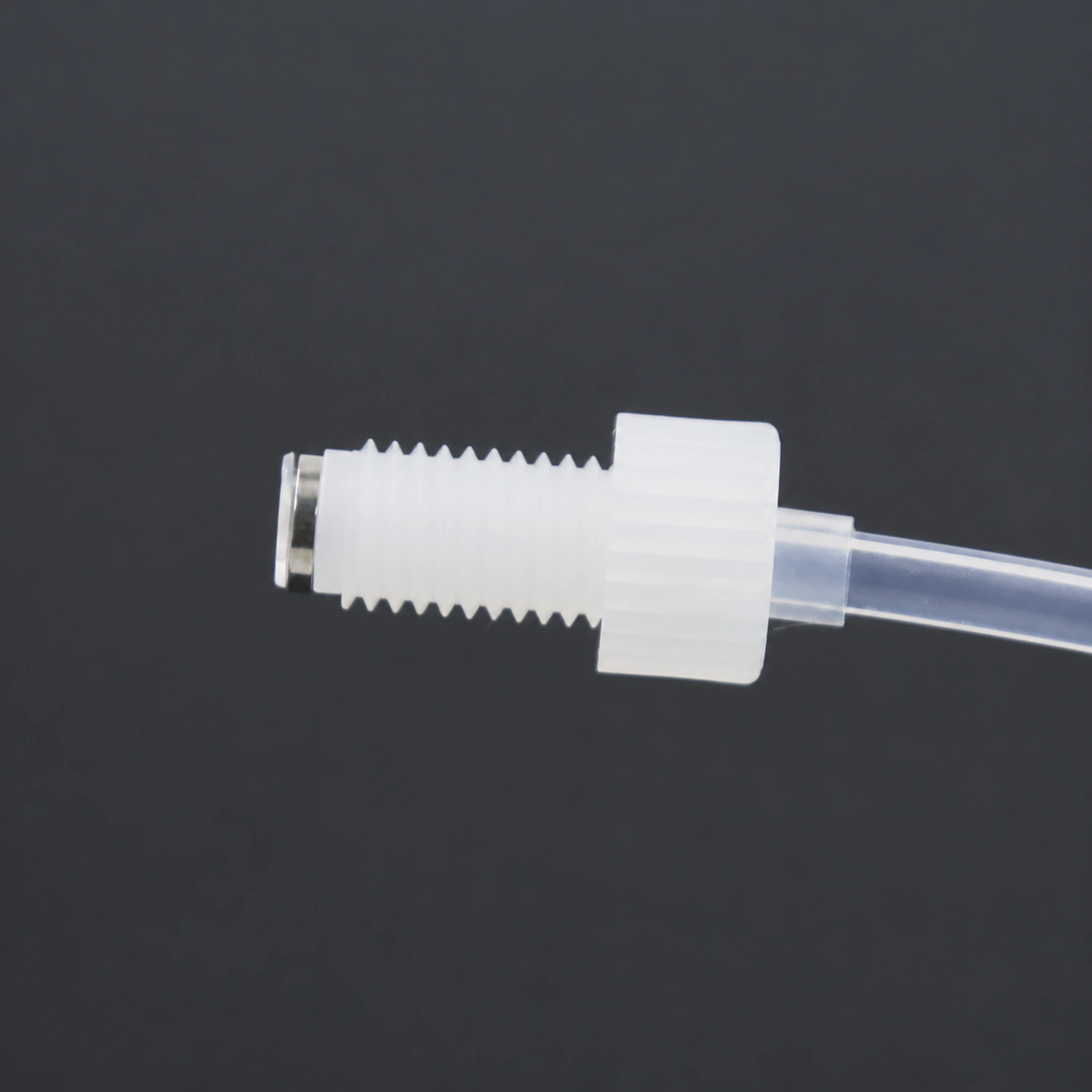
- Identify A/B fitting models, threads, sealing faces and required washers. Thread size alone is not a complete interface definition.
- Specify ID/OD, tolerance, finished length and length reference points, including straight sections, routing and fixing locations.
- Check end processing and assembly against port requirements to avoid uneven cuts, eccentricity, over-compression or bore constriction.
- Treat tubing, fittings and seals as one assembly, verifying working temperature/pressure, vacuum sealing and condition after reassembly.
1.6 mm and 1/16 inch are not identical. Even if a tube enters the fitting or the threads engage, verify permitted diameter, port depth and sealing position before confirming compatibility.
07How are PFA tubing temperature, pressure and long-term operation validated?
A resin temperature limit is not an assembly working temperature, and room-temperature burst pressure is not a long-term working pressure. For the selected tube size, length and ends, check allowable pressure and duration at working temperature, including changes from valve switching, pump starts/stops and blockages.
Polymer tubing can change dimensions under sustained load and temperature, altering grip and sealing stress at the ends. Long-term assessment should include pressure holding, temperature cycles, routing support, fitting retention and inspection after cleaning cycles. Extra tightening cannot replace structural compatibility.
- Define operating conditions: process and cleaning fluids, temperature, flow, continuous and peak pressure, and suction vacuum.
- Check assembly components: record models, dimensions, ports and tightening method; build samples using the same process.
- Validate operation: measure sealing, flow, bubbles, displacement and analytical background within the assembly's allowable conditions.
- Inspect after operation: check end deformation, loosening, leakage and analytical results; include acceptance conditions in the configuration requirements.
08FOREACH PFA tubing models and dimensions
| Model | Product code | ID × OD (mm) | Packaging |
|---|---|---|---|
| SF403002 | 439081 | 0.5 × 1.6 | 100 m/roll |
| SF403003 | 439082 | 0.8 × 1.6 | 100 m/roll |
| SF403004 | 439080 | 1 × 1.6 | 100 m/roll |
For rolls, retain model and pack unit. For fixed-length assemblies, also provide length, both end drawings, operating conditions and analytical requirements. Where cleanliness is specified, state the target test method and acceptance criteria explicitly.
10PFA tubing selection FAQ
1. Where is length measured on a PFA tubing assembly drawing?
Measure between the two reference points specified on the drawing. Cut-tube length is the length before end processing and assembly; assembled overall length is between specified outer-end references; sealing-face distance is between the two specified sealing faces. These are not interchangeable. Identify length type, reference points and tolerance. For curved routing, also specify whether length follows the tube centerline or is the straight-line distance between two points.