
What Is FEP Tubing? Properties, Dimensions and Connections for Transparent Fluoropolymer Tubing
FEP tubing is made from fluorinated ethylene propylene, a fluoropolymer with broad chemical resistance that can be melt-extruded into small-bore tubing. Transparent FEP makes filling, liquid levels and bubbles easier to observe and is commonly used for reagent transfer, wash-fluid supply and connections between pumps and valves in analytical instruments.
FEP tubing is often cut to the instrument's routing length and fitted with flanged, retaining-ring or ferrule connections to form an assembly comprising the tube and both end fittings. Select ID/OD, finished length and port geometry together, and choose color and wall thickness for the required visibility.
01What is FEP tubing made of, and why can it be transparent?
FEP, fluorinated ethylene propylene, is a copolymer of tetrafluoroethylene and hexafluoropropylene. It is a melt-processable fluoropolymer that can be continuously extruded into tubing. FEP and PTFE are both fluoropolymers, but differ in processing and finished-tube behavior. Specify the material explicitly when purchasing; fluoropolymer tubing alone is not a complete specification.
Transparent FEP tubing helps users observe liquid columns, filling fronts and larger bubbles. Actual visibility depends on wall thickness, tube size and color, liquid color and lighting. Black and other colored configurations serve different routing requirements and should not be assumed to provide the same visibility.
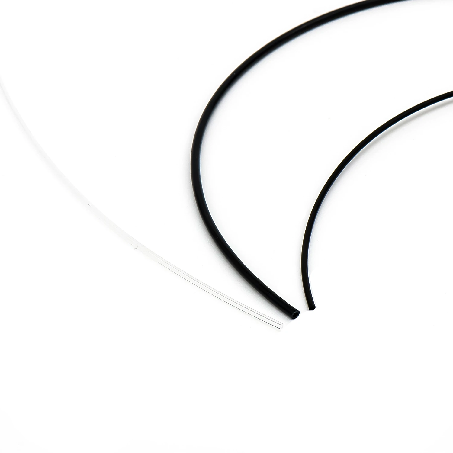
Transparent tubing is not automatically an optical flow cell. When fitting FEP tubing into a bubble sensor, level sensor or optical detector, match the sensor's tube-size, wall-thickness and optical requirements, then verify detection with the target liquid.
02How do FEP tubing properties affect instrument fluidics?
| No. | Characteristic | Role in fluidic design | Compatibility checks |
|---|---|---|---|
| 1 | Broad chemical resistance | Material selection for reagent, wash-fluid and solvent transfer | Check fluid composition, concentration, temperature and contact time |
| 2 | Transparent configurations aid observation | Observe filling, liquid levels and bubbles | Check wall thickness, color, lighting and sensor compatibility |
| 3 | Low surface energy | Assess adhesion and rinsing requirements | Evaluate cleaning through sample-residue and blank measurements |
| 4 | Melt processability | Enables continuous extrusion and suitable tube-end forming | Check finished-tube tolerances, flange dimensions and port geometry |
Apply chemical-compatibility checks to the complete wetted path. Even when the tube is compatible with the reagent, fitting bodies, sealing washers, valve seals or cleaning fluids can limit the assembly's use. Include transfer, soaking during shutdown and cleaning in the material assessment.
Tube surface properties cannot be converted directly into metering accuracy. Dispensing also depends on pumps, valves, bubbles, tubing compliance, connection dead volume and control timing. For low-volume transfer, measure actual delivery and repeatability in the complete fluid path.
03How should FEP, PTFE and PFA tubing be compared?
| Selection criterion | FEP | PTFE | PFA |
|---|---|---|---|
| Material and processing | Melt-processable perfluorinated copolymer | Small-bore tubing commonly uses paste extrusion and sintering | Melt-processable perfluoroalkoxy polymer |
| Observing liquid in the tube | Transparent configurations aid observation | Natural configurations are often milky white or translucent | Check actual visibility in transparent or translucent configurations |
| Reagent transfer | Select for the specific fluid and assembly conditions | Select for the specific fluid and assembly conditions | Select for the specific fluid and assembly conditions |
| Fixed length and end connections | Configure flanged, retaining-ring or ferrule connections for the tube size | Consider end processing and sustained gripping conditions | Select for tube size, formed-end dimensions and mating port |
First exclude unsuitable configurations based on fluid, temperature and pressure, then compare visibility, dimensions, connections and maintenance. FEP processing does not guarantee tighter tolerances than every PTFE tube, and the name PFA does not establish an entire fluid path's cleanliness grade. Compare finished-product specifications under the same acceptance conditions.
For degassed liquids or dissolved-oxygen-sensitive measurements, compare behavior for the target gas at the same wall thickness, temperature and length. Wall permeation, air ingress at fittings and gas coming out of solution are distinct issues. Changing tubing material alone cannot replace suction-line troubleshooting.
04Where is FEP tubing used in instruments?
- Bottle-to-pump/valve supply lines: assess fluid compatibility, vacuum sealing and suction resistance together. Transparent tubing helps with observing initial filling.
- Pump/valve-to-sampling-probe connections: choose ID and length for the volume per transfer, reducing unnecessary connections and hold-up space.
- Wash-fluid lines: check the cleaning agent, concentration, rinse temperature and contact time during shutdown.
- Low-pressure solvent lines in analytical instruments: route for the degassing location and flow, and check bubbles, dimensions and sealing after solvent exposure.
Ordinary FEP connection tubing cannot directly replace roller-compressed peristaltic pump tubing. That section requires repeated compression, recovery and fatigue resistance; use tubing matched to the pump head. FEP can be used in connections before and after the pump, with the connection locations and transition fittings included in the fluidic design.
05How do FEP tubing ID and length affect flow resistance and displacement volume?
ID determines flow area, while length determines travel distance and contained volume. For fully developed laminar flow in circular tubing, pressure drop is more sensitive to ID than to length. Smaller IDs increase pressure drop at the same flow; larger IDs increase the volume required for filling and displacement.
ΔP = 128μLQ / (πd⁴);V = πd²L / 4
ΔP: pressure drop; μ: dynamic viscosity; L: tube length; Q: volumetric flow rate; d: ID; V: geometric internal volume. Applies to steady, incompressible Newtonian fluid in fully developed laminar flow through a circular tube without significant deformation. Evaluate fitting losses, pump pulsation and bubbles separately.
At equal length, increasing ID from 0.5 mm to 1.0 mm reduces ideal laminar hydraulic resistance to 1/16 and increases internal volume fourfold. This is a dimensional relationship, not a difference in material performance. In actual selection, consider available pump differential pressure, viscosity, permitted residue and the cleaning procedure together.
- Establish target flow, viscosity and available differential pressure, then estimate ID.
- Determine length from the instrument layout, calculate filling and displacement volumes, and check bends for constriction.
- Include fitting, valve and filter resistance, then verify flow and displacement in the actual fluid path.
06How are FEP tubing, flanged fittings and fixed-length assemblies configured?
FEP tubing can form flanged tubing assemblies or use retaining-ring or ferrule connections according to the port. A flanged connection joins a formed tube end with its matching washer and fitting. Retaining-ring and ferrule designs have their own gripping and sealing mechanisms; matching threads alone do not make them interchangeable.
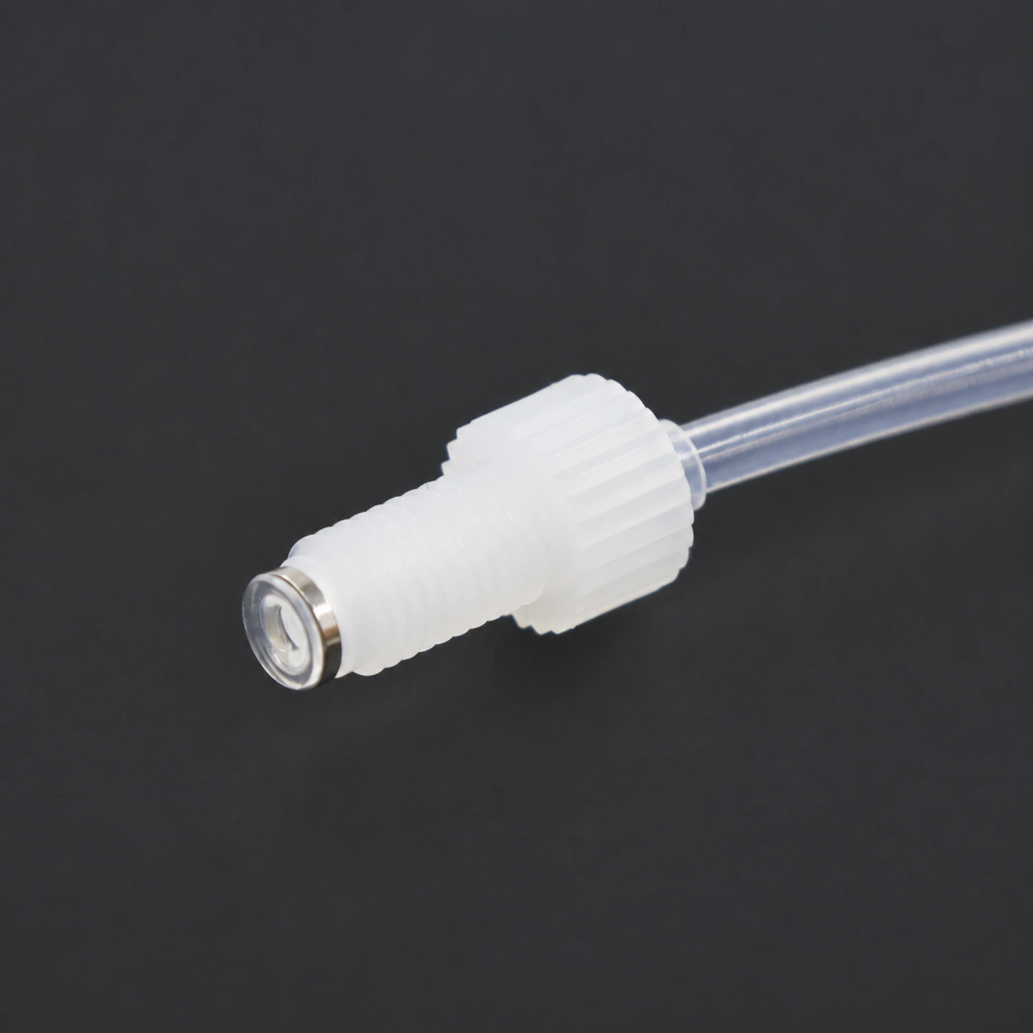
- Specify material, ID and OD. ID serves flow and internal-volume requirements; OD and its tolerance govern connection fit.
- Identify fittings, threads and port sealing faces at ends A and B. Check the relationship between flange geometry, washers and fittings.
- Dimension overall length and its reference points, single or double flanging, routing and fixing positions so the drawing matches installation.
- Assemble as specified and verify sealing and retention under working pressure, suction vacuum and temperature cycling.
A 1/16-inch OD equals 1.5875 mm, close to but not identical to 1.6 mm. The same connection can serve both only if the fitting's permissible range includes the actual tube diameter. Extra torque cannot compensate for mismatched ports or dimensions.
07How are FEP tubing temperature, pressure and cleaning conditions determined?
Allowable working pressure depends on tube diameter, wall thickness, temperature and end connections. Use operating conditions for the selected tubing/fitting combination; resin temperature limits, room-temperature burst pressure and assembly working pressure are different quantities. Include pressure peaks from pump starts/stops, valve switching and blocked outlets.
Under suction vacuum, also check wall deformation, local kinks and air ingress at fittings. No liquid leakage under positive pressure does not replace a vacuum-sealing check. Tight bends and over-tightened mounting clips can also change suction performance.
Specify fluid, temperature, contact time and cycle count for cleaning or sterilization, then assess dimensions, mechanical condition and wetted-path background. Material behavior under one treatment does not establish suitability for every finished tube, fitting and seal.
08Which FOREACH FEP tubing sizes and assembly options are available?
| Model | ID × OD (mm) | Packaging |
|---|---|---|
| BFT03001 | 0.3 × 1.6 | 100 m/roll |
| BFT03002 | 0.5 × 1.6 | 100 m/roll |
| BFT03003 | 0.8 × 1.6 | 100 m/roll |
| BFT03004 | 1 × 1.6 | 100 m/roll |
| BFT03007 | 1 × 2 | 100 m/roll |
| BFT03008 | 1.5 × 2.5 | 100 m/roll |
| BFT03010 | 1.6 × 3.2 | 100 m/roll |
| BFT03009 | 2 × 3 | 100 m/roll |
Alongside tubing rolls, FEP is available in flanged, retaining-ring and ferrule tubing assemblies. For customization, provide length, both end connections, mating-port drawings and acceptance conditions to turn a tubing model into an installable assembly configuration.
09What should be checked before installing FEP tubing?
- Check model, ID/OD, length and batch; inspect cuts, walls, flanges and appearance.
- Verify compatibility with the actual reagent and cleaning fluid at working concentration, temperature and contact time.
- Assemble to the port drawing, then check sealing, retention and tube deformation under both supply pressure and suction vacuum.
- Check filling, bubble detection and liquid-level visibility under actual lighting and sensor conditions.
- After continuous operation and cleaning cycles, recheck flow, displacement volume, residue and end condition.
Acceptance records should identify the model, assembly drawing and operating conditions. After changing ID, length, color or fittings, reassess the affected transfer and detection functions.
11FEP tubing selection FAQ
1. What dimensions and fitting information are needed for a custom FEP flanged tubing assembly?
Provide FEP tube ID, OD, tolerances and color; specify single- or double-flanged ends and identify both fittings, threads, washers and mating ports. Define length reference points and distinguish cut-tube length from assembled length. Label ends A and B separately if their configurations differ. Also provide fluid, temperature, pressure or vacuum, and dimensional and sealing acceptance requirements.