
How Do You Choose Between a 300 mL/min and 600 mL/min Miniature Diaphragm Pump? Calculate Task Flow First, Then Check the Actual Operating Point
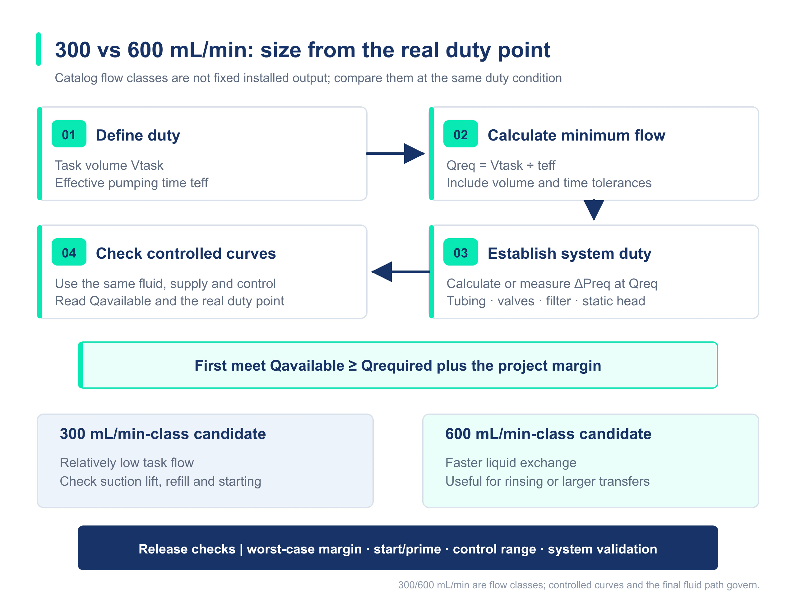
The 300 mL/min and 600 mL/min values are flow classes first, not fixed outputs after installation in an instrument. Selection should begin by converting the liquid-handling task into a minimum average flow rate, then determining the differential pressure required by the actual fluid path, and finally confirming the operating point on the pump curve and in prototype testing.
For washing, fluid replacement, priming, circulation and waste-drain tasks, an instrument does not really need a catalogue number detached from its conditions. It needs to move the target volume within the specified time and under the specified fluid-path conditions. The 300 mL/min and 600 mL/min pump classes become comparable only when flow and pressure are placed at the same operating point.
1. Put the ‘300’ and ‘600’ Values Back into Their Test Context
A 300 mL/min or 600 mL/min miniature diaphragm pump specification usually describes the free-flow rate or maximum flow under a defined fluid, power supply and low differential-pressure condition. Once the pump is installed in an instrument, suction tubing, discharge tubing, valves, fittings, filters, flow cells, needles, liquid-level differences and fluid viscosity all change the differential pressure across the pump, shifting the actual flow to another point on the curve.
| Quantity to compare | Correct meaning | Incorrect interpretation |
|---|---|---|
| Free-flow rate | Flow endpoint or flow class under a defined low-load condition | The instrument can continuously deliver this flow at any backpressure |
| Rated pressure | Permissible pressure capability under defined conditions | The pump still maintains its free-flow rate at this pressure |
| Actual operating point | Intersection of the pump curve and the current system curve | Can be determined from the pump model or static outlet pressure alone |
2. Step One: Calculate the Minimum Flow from Task Volume and Effective Pumping Time
Qrequired = Vtask ÷ teffectiveVtask is the volume transferred, washed or drained in one task, and teffective is the time actually available for pumping in the program. If V is in mL and t is in min, the result is directly in mL/min. If t is in s, first obtain mL/s and then multiply by 60 to convert to mL/min.The instrument cycle time is often not the same as effective pumping time. Valve switching, liquid-level detection, soaking, venting and control delays consume part of the cycle, so these non-pumping stages must be deducted from the total cycle time. If the program contains a short, rapid-rinse stage, define the average requirement and the peak-stage requirement separately.
| Illustrative task (not a customer case) | Task volume | Effective pumping time | Minimum average flow | Key follow-up check |
|---|---|---|---|---|
| Small-volume priming | 120 mL | 45 s | 160 mL/min | Starting, self-priming and venting |
| Rapid washing | 400 mL | 60 s | 400 mL/min | Tubing pressure drop at high flow |
| Waste-drain cycle | 250 mL | 50 s | 300 mL/min | Liquid-level change and terminal backpressure |
3. Step Two: Write the Fluid-Path Resistance as a Directional Pressure Budget
First define the direction of flow from the source to the terminal end and consistently use either gauge pressure or absolute pressure. The differential pressure that the system requires the pump to provide at target flow Q can be itemized as follows; both distributed losses and local losses are taken as positive in the direction of flow.
ΔPrequired(Q) = ΔPdistributed(Q) + ΣΔPlocal(Q) + [Pterminal − Psource] + ρg[zterminal − zsource]zterminal − zsource is a signed elevation difference: it is positive when the terminal end is above the source, meaning the pump must overcome hydrostatic pressure; it is negative when the terminal end is below the source, meaning gravity assists the flow. Pterminal − Psource is also calculated with its sign using the same pressure reference.This relationship helps prevent omissions; it does not imply that every component can be predicted accurately with one simplified formula. For critical components such as filters, valves, needles and flow cells, use the manufacturer's pressure-drop curve at the corresponding flow or measured data whenever possible. The suction side also requires a separate check of inlet absolute pressure, replenishment and cavitation risk.
| Resistance source | Why it changes | Selection impact |
|---|---|---|
| Tubing | Differences in inner diameter, length, bends and soft-tube deformation | The same pump delivers different flow in different tubing layouts |
| Valves and fittings | Differences in internal bore, Cv/Kv and local restrictions | May become the bottleneck in the complete fluid path |
| Filter | Different pressure drop when new and after loading | Should cover the condition near the replacement point |
| Liquid level and vessel pressure | Changes in source level, terminal elevation or vessel pressure | Changes the hydrostatic term and inlet conditions |
| Terminal structure | Resistance from a needle, nozzle, positive-pressure chamber or flow cell | May turn a flow problem into a high-backpressure problem |
4. Foreach Published Parameters Show Why More Flow Does Not Mean More of Every Capability
Published Foreach data for the DPL30 and DPL60 illustrate the different parameter dimensions. Their free-flow classes differ, their published rated pressure is the same at 100 kPa, and their self-priming lifts are 6 mH₂O and 3 mH₂O, respectively. Flow, self-priming and pressure must be checked separately.
| Comparison dimension | Representative DPL30 parameter | Representative DPL60 parameter | Selection meaning |
|---|---|---|---|
| Published free-flow rate | 300 mL/min | 600 mL/min | Low-differential-pressure endpoint, not a guaranteed installed value |
| Published rated pressure | 100 kPa | 100 kPa | Read the available flow at the target pressure |
| Published self-priming lift | 6 mH₂O | 3 mH₂O | Higher flow does not mean greater self-priming lift |
| Common connection | 3.2 mm ID soft tubing | 3.2 mm ID soft tubing | The same interface does not mean the same system resistance |
| Priority evaluation scenario | Lower task flow or greater emphasis on suction lift | Larger-volume transfer, rapid fluid replacement or washing | The actual operating point remains the final basis |
If the main restriction comes from a fine needle, narrow tubing, filter or positive-pressure chamber, check the total differential pressure at the target flow first. If a conventional flow platform lacks sufficient capability in this region, evaluate a higher-pressure platform such as the DPL30H instead of simply replacing 300 mL/min with 600 mL/min.
View theDPL30 liquid diaphragm pump.
View theDPL60 liquid diaphragm pump.
Learnhow to read a miniature diaphragm pump flow-pressure curve.
For inkjet supply and return circuits, read the300 vs 600 mL/min Ink Circulation / Return Pump guide.
5. Compare Candidate Pumps at the Same Operating Point
- Document the volume per task, effective pumping time, daily cycle count and whether there is a peak-flow stage.
- Draw the complete fluid path from the source to the terminal end, recording tube diameter, tube length, valves, fittings, filters, needles, chambers, vessel pressure and the signed elevation difference.
- Calculate or measure inlet losses, outlet losses and the differential pressure across the pump at the target flow.
- Align the fluid, temperature, power supply, speed and pressure definition used for each candidate pump curve, then read the available flow near the target differential pressure.
- Cover the lowest liquid level, filter loading, lowest permissible voltage, fluid limits and sample variation, and confirm that the task is still met under the worst-case condition.
- Then check self-priming, materials, life, noise, temperature rise, control range and installation space, and release the design in the complete prototype.
6. Prototype Validation Should Cover Baseline and Worst-Case Conditions
| Variable | Baseline condition | Worst-case condition | Recommended record |
|---|---|---|---|
| Reservoir liquid level | Highest or typical liquid level | Lowest permissible liquid level | Inlet pressure, start time and flow |
| Filter | New component | Equivalent pressure drop near the replacement point | Filter differential pressure and pump flow |
| Power supply | Rated voltage | Lowest permissible voltage at the pump | Voltage, current, speed and starting |
| Fluid | Baseline temperature and viscosity | Permissible limit | Flow, bubbles and valve response |
| Pump samples | Multiple initial samples | Low-performance samples or samples at a life stage | Mean, spread, trend and leakage |
Conclusion: Select the Operating Point That Meets the Task, Not the Larger Catalogue Number
A 300 mL/min-class pump may be more suitable when task flow is lower and suction lift matters more, while a 600 mL/min-class pump may be more suitable for rapid fluid replacement and larger-volume transfer. Any conclusion, however, must also specify pressure, liquid level, fluid, power supply and fluid-path version. Putting task flow, system differential pressure and the pump curve into the same validation table is the way to avoid undersizing and ineffective oversizing.
FAQ | Selecting a 300 mL/min or 600 mL/min Miniature Diaphragm Pump
If an instrument requires 300 mL/min, should I select a 600 mL/min pump directly to leave margin?
No. First define the differential pressure, liquid level, fluid and effective pumping time associated with the 300 mL/min requirement, then read the candidate pump curve. An oversized platform may also reduce low-speed control resolution and increase noise, pulsation, power consumption and space cost.
Is a 600 mL/min pump adjusted to 300 mL/min equivalent to a 300 mL/min pump?
No. The two product classes may differ in pump chamber, valve response, self-priming, pulsation, motor and low-speed stability. Speed adjustment also changes the pump curve, so testing is required at the target speed and actual backpressure.
Why are the DPL30 and DPL60 not interchangeable even though both have a rated pressure of 100 kPa?
Rated pressure is only one dimension. Differences in free-flow rate, self-priming lift, power, structure, operating curve and control range determine their different usable operating regions in an instrument.
When should a design move from a conventional flow platform to a high-pressure diaphragm pump?
When the total system differential pressure at the target flow approaches or exceeds the usable curve of a conventional pump, and the main resistance comes from a fine needle, narrow tubing, filter, positive-pressure chamber or high-resistance terminal component, evaluate a higher-pressure platform and simultaneously verify the permissible working pressure of the entire fluid path.