
Flow starts normally, then falls: how do you check reservoir venting for a miniature diaphragm pump?
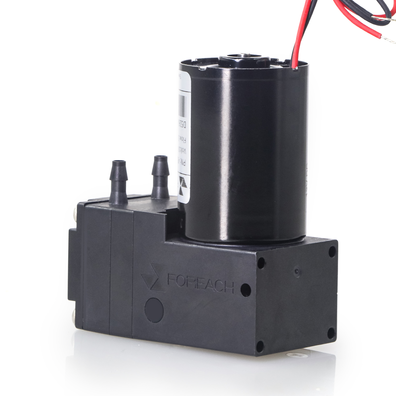
A miniature diaphragm pump that initially delivers normally and then slows down is not necessarily damaged. When drawing from a reservoir, one useful check is whether gas can replace the withdrawn liquid as intended. Falling delivery can also result from a changing liquid level, filters, tubing or outlet load. The symptom alone does not establish a blocked vent.
1. Identify how the container compensates for withdrawn liquid
Rigid bottles, collapsible bags and pressure-controlled reservoirs work differently. A rigid bottle commonly needs a designed gas-exchange or pressure-control path. A collapsible bag can compensate through deformation, while a pressurized reservoir requires its regulator and gas supply to be checked. Review the fluid schematic and container instructions before deciding whether a sealed condition is abnormal.
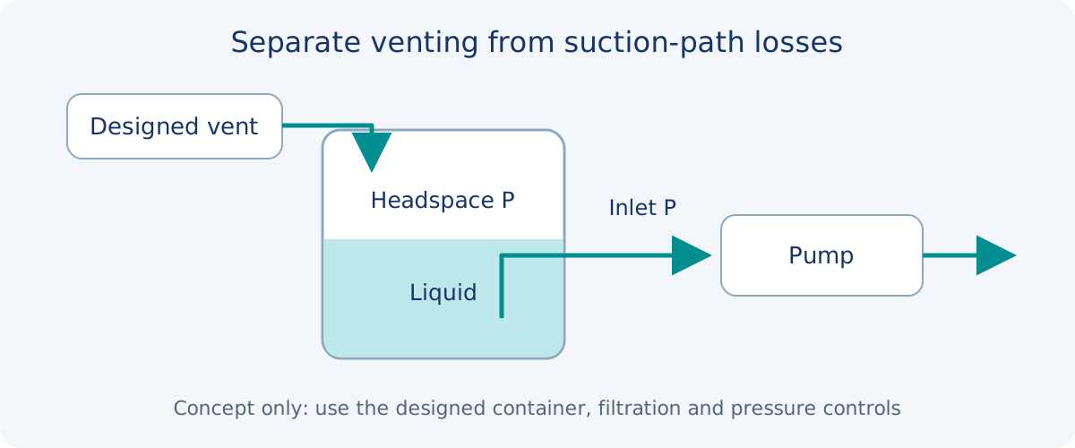
For a vented rigid bottle, inspect the complete gas path: ambient inlet, filter, connecting tube, cap fitting and internal opening. A visible hole does not prove adequate vent capacity during operation. A wetted membrane, kinked line or submerged internal opening can change the effective pressure loss.
2. Why a sealed rigid bottle can become harder to empty
Consider an explanatory model: a completely sealed rigid bottle, a fixed amount of gas at constant temperature, with evaporation, dissolved gas and leakage temporarily neglected. Removing liquid expands the headspace and lowers its absolute pressure.
P₂,abs = P₁,abs × Vg₁ / (Vg₁ + ΔVliquid)Isothermal ideal-gas approximation for a fixed gas quantity. P is absolute pressure, Vg₁ is initial headspace volume and ΔVliquid is withdrawn liquid volume. Do not substitute gauge pressure.Assume an initial 100 mL headspace at 101.3 kPa absolute. After withdrawing 20 mL, the model gives 101.3 × 100/120 ≈ 84.4 kPa absolute, or approximately −16.9 kPa gauge relative to the original ambient pressure. These are illustrative calculations, not measurements from a Foreach pump or a real reservoir.
Real containers can deform or leak; liquids can evaporate or release dissolved gas; temperature can change. Consequently, withdrawn volume alone does not determine actual headspace pressure. The model explains why restricted gas replacement can progressively burden suction. Measurements are still needed for diagnosis.
3. Separate headspace pressure from suction-path losses
Pinlet,abs ≈ Pheadspace,abs + ρg(zsurface − zinlet) − ΔPsuctionApproximate steady relation using consistent pressure units. ρ is liquid density and z is elevation. Fast pulsation, acceleration and two-phase flow require further analysis.Falling headspace pressure, a falling liquid level and increasing suction-path resistance can all reduce pump inlet pressure. Measuring the headspace helps identify container gas-replacement conditions. An additional inlet measurement shows the combined influence of the liquid column and pickup path. Outlet flow alone cannot reliably distinguish these causes.
Diaphragm pump suction varies over the cycle. A slow sensor may report only an average, which cannot rule out brief suction problems. Instrumentation should not introduce a new air leak or significant dead volume.
4. Use observations and controlled comparisons to narrow the cause
| Possible cause | Evidence to examine | Follow-up check |
|---|---|---|
| Restricted gas replacement | Headspace pressure drifts outside its intended condition while delivery changes | Check gas-path pressure loss and compare an approved, verified vent component on a controlled bench |
| Falling liquid level or changing lift | Headspace pressure is normal but inlet conditions track liquid height | Repeat at the same level and installation height |
| Blocked pickup filter or deformed tube | Normal headspace pressure with increased suction-path pressure difference | Inspect the filter, fittings and bends, changing one factor at a time |
| Air entry at the inlet | Bubbles or temporary recovery after priming | Check connection integrity; visible bubbles are not the only evidence |
| Changing outlet load | Outlet pressure rises as delivery falls | Inspect downstream valves, nozzles, tubing and receiving-vessel pressure |
| Electrical, thermal or liquid changes | Voltage, current, temperature or viscosity-related conditions change | Hold other conditions constant before comparing |
These observations organize the investigation; no row is a unique fault signature. For example, increasingly negative inlet pressure can arise from restricted venting or a blocked liquid pickup filter. Combine pressure locations with controlled comparisons.
5. Make the venting check reproducible
- Record container type, pressure and vacuum ratings, liquid, temperature, initial level, headspace volume, installation height and the designed vent path.
- At the same electrical and control conditions, record elapsed time, cumulative withdrawal, flow, headspace pressure, inlet pressure and outlet pressure. Retain voltage, current and liquid-level information.
- Inspect gas and liquid paths before and during the symptom. Look for filter wetting, liquid in the vent line, a submerged gas opening or tube deformation.
- If comparison is needed, use a controlled bench with water or another suitable substitute and replace the vent component only through a method permitted by the design. Keep initial level, temperature, tubing and timing consistent.
- Compare pressure histories and delivered volumes before and after the change. Improvement in both, supported by component inspection, strengthens the diagnosis; brief flow recovery by itself is insufficient.
Acceptance should cover the intended liquid-level range, longest operating period and peak withdrawal demand. Running for a few seconds from a full bottle is insufficient. Pressure limits and test duration must come from the container restrictions, pump inlet requirements and instrument duty.
6. Size the gas path against demand and allowable pressure loss
Under approximately equal pressure and temperature conditions, incoming gas volume flow generally needs to replace the liquid volume being removed. Normalize gas-flow ratings to compatible reference pressure and temperature before comparing them. A filter flow rating is meaningful only with its associated pressure difference and test conditions.
| Selection input | Data to obtain |
|---|---|
| Maximum withdrawal demand | Concurrent and peak liquid flow, with the corresponding gas-replacement requirement |
| Allowed headspace pressure deviation | Container ratings, pump inlet requirements and process constraints |
| Gas-path pressure loss | Filter, tube and fitting loss at relevant gas flow |
| Wetting and chemical exposure | Liquid and vapor compatibility, installation orientation and drainage |
| Service and maintenance | Supplier replacement criteria and a method for detecting abnormal pressure loss |
A larger opening alone is not a complete selection rule. Do not assign a membrane pore size or universal vacuum alarm without the application requirements. Filtration, contamination control, chemical compatibility and gas-path resistance must be assessed together.
7. Return to pump selection after checking the supply conditions
Restore the reservoir, inlet path and outlet load to their intended conditions, then assess whether the pump can complete the task. The 300 mL/min DPL30 and 600 mL/min DPL60 flow classes provide starting points for a shortlist, while usable delivery still depends on operating pressure, liquid and inlet conditions.
When gas replacement or the suction path is restricted, a larger pump can increase instantaneous withdrawal demand and does not guarantee recovery. Once the system conditions are established, use the relevant curve and assembled-system measurements to decide whether the pump model, tube bore or control timing needs to change.
Suction-side versus discharge-side resistance
Troubleshooting reduced self-priming performance
Motor running with no liquid delivery
Flow–pressure curves and the actual operating point
DPL30 liquid diaphragm pump selection guide
DPL60 liquid diaphragm pump selection guide
Frequently asked questions
Does recovery after opening the cap prove the pump is healthy?
It shows that changing the container boundary conditions affected delivery. It does not alone exclude pump issues or inlet leaks. Confirm the cause with an approved vent comparison and synchronized pressure measurements.
Why can a bottle with a vent still develop vacuum?
Gas needs a pressure difference to pass through filters, tubing and fittings. A small, obstructed, wetted or submerged path may not replace gas at the rate required by liquid withdrawal.
Should every sealed container have a vent hole?
No. Collapsible bags, pressurized reservoirs and controlled-atmosphere containers use their own volume-compensation or pressure-control methods. Check the intended design instead of converting every container into an open vessel.
At what vacuum should an alarm trigger?
Set it from the container rating, pump inlet conditions and instrument performance requirements. The −16.9 kPa value in this article is a hypothetical calculation, not an alarm setting or allowable product pressure.
Will a larger pump prevent the gradual flow drop?
That cannot be assumed. Resolve restricted gas replacement or inlet supply first, then verify the pump against the required delivery and operating duty at the actual working conditions.