
Why do multiple wash nozzles deliver different flows from one miniature diaphragm pump?
One pump and one manifold do not guarantee equal delivery at every wash nozzle. A clinical chemistry analyzer or another instrument with parallel wash paths needs two checks: sufficient total flow at the actual operating pressure, and acceptable delivery through each branch. A total-flow measurement alone can conceal an under-supplied nozzle. All numerical examples below are hypothetical calculations, not measured product results.
1. Define the wash task at each nozzle
Replace a general request for a wash pump with measurable requirements: the number of simultaneously active nozzles, the volume required per nozzle, the open-valve window, whether pre-filling is allowed, and the acceptance criteria for the first and subsequent cycles. Sequential operation changes both peak flow demand and the time needed to complete a batch.
| Required input | Why it matters | What to record |
|---|---|---|
| Volume and tolerance per nozzle | Sets the delivery requirement for each branch | Individual collected volumes, not only their average |
| Effective delivery time | Priming, startup and valve delays consume the window | Delay between the command and actual liquid delivery |
| Number of open branches | Sets peak simultaneous demand | Normal and maximum concurrency |
| Liquid, temperature and fluid path | Affects resistance, compatibility and operating point | Liquid batch, temperature, bore, length and components |
2. Calculate total demand from individual delivery volumes
Assume four nozzles operate together and each must deliver 3 mL in two seconds of effective liquid delivery. Each branch requires an average of 90 mL/min, giving a total of 360 mL/min. If two seconds is only the controller command window, subtract any interval without useful delivery before calculating the requirement.
Qᵢ = 60 × Vᵢ / tᵢ; Qtotal = ΣQᵢWith V in mL and t in seconds, Q is in mL/min. Sum concurrently active branches; this example includes no separate bypass or return flow.Foreach DPL30 and DPL60 selection guides describe 300 mL/min and 600 mL/min flow classes respectively. The DPL30 nominal figure does not establish that it can meet this hypothetical 360 mL/min duty. DPL60 is a candidate for further evaluation: its 600 mL/min figure is not automatically the flow available through the installed tubing, valves and nozzles. Confirm the operating point at the specified voltage, liquid, inlet conditions and required outlet pressure.
3. Adequate total flow does not establish equal distribution
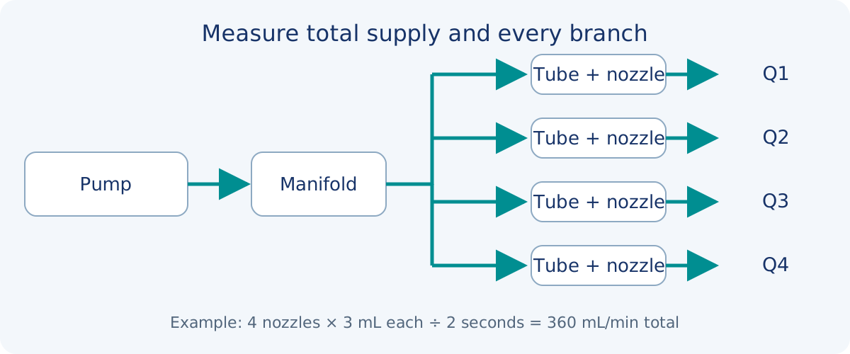
For steady, approximately incompressible flow without a bypass or significant fluid storage, total flow equals the sum of branch flows. Each branch still responds to its own effective pressure difference and resistance. A common-pressure approximation is useful only when manifold inlet pressures, outlet pressures and elevation conditions are sufficiently similar.
The common supply tube and manifold inlet carry total flow; each downstream tube carries only its own branch flow. Applying total flow to every branch calculation overstates branch losses. Applying one branch flow to the common tube understates shared losses.
| Source of difference | Possible observation | Where to inspect |
|---|---|---|
| Bore, length or tube deformation | One branch remains consistently low | Tube tolerances, insertion depth, bends and pinched sections |
| Nozzle or valve differences | The low-flow position follows a swapped component | Nozzle bore, contamination, valve opening and timing |
| Outlet elevation or immersion | Distribution changes after installation changes | Nozzle height, immersion and receiving-vessel pressure |
| Bubbles or compliant storage | The first cycle differs from later cycles | Trapped gas, tube expansion and priming state |
4. Use bore sensitivity as a diagnostic model
ΔP = 128 μ L Q / (π d⁴)For steady, fully developed laminar flow of a Newtonian liquid in a rigid circular straight tube. μ is dynamic viscosity, L is length and d is internal diameter. Consistent SI units give pressure loss in Pa.For an otherwise identical ideal tube segment, a 10% smaller bore gives about 1/0.9⁴ = 1.52 times the resistance. At the same pressure difference, flow becomes approximately 0.9⁴ = 65.6% of the original value. This calculation describes sensitivity in one idealized segment; it does not predict a 34.4% reduction for the complete pump system.
An installed path also contains nozzle openings, fittings, valves, filters and pulsating flow. Short orifices, developing flow, turbulence or strongly deformable tubing need appropriate models or component data. Use available pressure-loss curves and verify the actual assembly. Changes to the network can also move the pump operating point.
5. Measure the total and every branch in the same test
- Prime the system as designed. Fix the liquid, temperature, supply voltage, reservoir level, installation height and tubing. Label each nozzle and collection vessel.
- Collect each branch over the actual control sequence. Calculate Qᵢ = Vᵢ/t where useful; for a short wash pulse, delivered volume per event is the primary measurement.
- Record inlet, outlet or manifold pressure with sensor locations, ranges and sampling rates. A slow average may hide opening transients.
- Compare the summed branch collection with total delivery over the same window. Account separately for bypass flow, return flow, leakage and changes in stored liquid.
- Evaluate startup, repeated operation and maximum concurrency separately. Set repetitions and acceptance limits from the instrument wash requirements before testing.
If total delivery passes but one branch fails, investigate distribution and timing. If every branch is low, use pressure measurements to distinguish insufficient supply from common-path losses, inlet limitations or electrical supply issues. When swapping a suspect nozzle or tube, change one factor at a time and observe whether the deviation follows that component.
6. Compare changes against both timing and pressure
| Change | Potential benefit | What must be checked again |
|---|---|---|
| Standardize branch dimensions and assembly | Reduces manufacturing and routing differences | Nozzles, valves and outlet elevations still matter |
| Add controlled resistance to higher-flow branches | Can balance a specified operating condition | Consumes pressure margin and changes total flow |
| Use grouped or sequential washing | Reduces simultaneous demand | Recalculate batch timing, valve duty and controls |
| Change the pump or improve the common supply path | Can improve total delivery at the operating point | Does not automatically remove unequal branch resistance |
Start with the delivery required by the failing branch. Raising voltage, selecting a larger pump or adding restrictors without individual measurements may change the total while leaving the root cause unresolved. Repeat the same acceptance method after adjustment, including every nozzle, the first cycle and total wash timing.
7. Continue to the related selection guides
This page addresses distribution from one pump into several wash paths. Pump selection also requires liquid compatibility, actual pressure and control requirements. If delivery declines with running time, investigate reservoir venting and the inlet supply as a separate condition.
Wash and rinse pump selection for instrument fluid paths
Using a flow–pressure curve to locate the operating point
How tube bore affects miniature diaphragm pump flow
DPL30 liquid diaphragm pump selection guide
DPL60 liquid diaphragm pump selection guide
Frequently asked questions
Can I divide total flow by the nozzle count?
That gives an average, not proof that every nozzle meets its requirement. Collect individual delivery volumes over the same command window and check the minimum delivery and permitted variation.
Do equal tube lengths guarantee equal flow?
No. Bore, nozzles, valves, fittings, outlet elevation and trapped gas also matter. Equal length addresses only one part of assembly consistency.
Will a 600 mL/min pump solve the problem?
More supply capacity is relevant when total flow at the actual operating point is insufficient. Unequal branch resistance still requires separate attention, and the nominal flow must be checked against the pump curve.
Should I measure average flow or volume per wash?
Average flow can help diagnose continuous delivery. For short wash events, include delivered volume and completion time because startup, priming and valve movement can occupy a substantial part of the window.
What percentage of imbalance is acceptable?
There is no single limit for all instruments. Derive the acceptance criteria from cleaning performance, residual-contamination requirements and the measurement method, then allocate tolerances across the pump, valves, tubing and controls.