Foreach TechnologyForeach Technology
Home
Products
Applications
About Us
Contact & Partnership
简体中文EnglishEspañolFrançais한국어Русский
Home
Products
Pump SeriesValve SeriesTubing SeriesFitting SeriesProbe SeriesSmart Control SeriesTubing Assemblies
Applications
All applicationsIVD DiagnosticsLife SciencesLaboratory AutomationAnalytical InstrumentsEnvironmental MonitoringSynthetic Biology
Resources
DatasheetsFluid Resistance CalculatorFitting ReplacementInstallation GuidesMaterial CompatibilityTechnical ArticlesCompany News
About Us
About ForeachR&D and ManufacturingQuality System and QualificationsMilestonesForeach Culture
Contact & Partnership
Contact UsBecome a Distributor
  • Pump Series
  • Valve Series
  • Probe Series
  • Fitting Series
  • Tubing Series
  • Control Series
  • Tubing Assemblies
  • All applications
  • IVD
  • Life Science
  • Lab Automation
  • Analytical Instruments
  • Environmental Monitoring
  • Synthetic Biology
  • Datasheets
  • Fluid Resistance Calculator
  • Fitting Replacement
  • Installation Guides
  • Material Compatibility
  • Technical Articles
  • Company News
  • About Foreach
  • R&D & Manufacturing
  • Quality & Compliance
  • History
  • Foreach Culture
  • Inquiry Form
  • Contact Information

Shenzhen Foreach Technology Co., Ltd.

Address: 13th Floor, 2nd Building, Yufengda Industrial Park, 1008th Guang Qiao Boulevard, Guangming District, Shenzhen 518132 CHINAView Map

Email: [email protected]

Tel: +86 755 8655 3831

LinkedInYouTubeFacebookInstagramX

© 2026 Shenzhen Foreach Technology Co., Ltd. All rights reserved.

Privacy Policy·

Home/Applications/In Vitro Diagnostics/Hematology analyzer
< Back

Diaphragm pumps in hematology analyzers

Application guide

Focusing on auxiliary cleaning, liquid supply and suitable aerated wash-fluid removal in hematology analyzers, this page explains diaphragm-pump location, coordination and configuration conditions, linking to related operating and validation tasks.

Applicable architecture

Hematology analyzers may use different detection principles and channel configurations. Diluent, lysing reagent and sheath-fluid locations depend on the specific method; sheath-flow conditions do not apply to every counting channel.[5]

Application guide

Hematology analyzer

Hematology analyzer
Diaphragm pumps in hematology analyzers
Hematology-channel cleaning and waste removal
Bubble and pressure sensing in hematology analyzers
Tubing and fittings in hematology analyzers
Multiport rotary valves in hematology analyzers
Detection-channel switching and fluid renewal
Piston pumps in hematology analyzers
Whole-blood sampling and delivery
Sampling probes in hematology analyzers
Syringe pumps in hematology analyzers
Diluent and reaction-reagent metering

On this page

What do these products do in this instrument?Define liquid-supply and aerated-aspiration branches separatelyMatch supply/removal capacity to washing-station and container conditionsTranslate actual branch conditions into configuration requirementsCompare product configurations by the roles on this pageExplore specific operating and validation tasksConfirm product roles in actual operationDo similar nominal supply- and waste-pump flow rates make a matched pair?ReferencesRelated guides

01What do these products do in this instrument?

Liquid diaphragm pumps: auxiliary cleaning and liquid supply

Supply liquid to the installed cleaning or auxiliary branches, coordinated with channel flushing and waste destinations. Where detection requires specific flow or pressure, confirm the drive configuration separately for that channel.

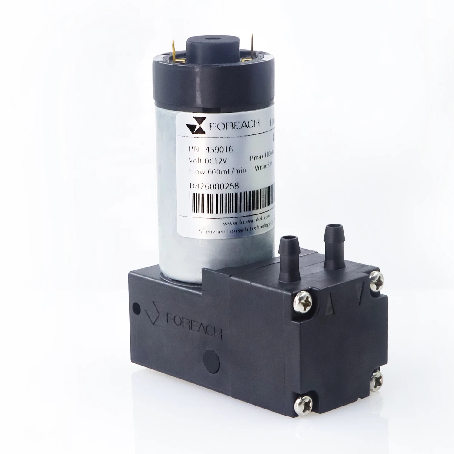
Compare DPL30, DPL60 and DPL30H by actual supply load. Wash-head, valve, tubing and container resistance jointly determine installed flow; check the supply window and receiving position together.

Gas–liquid diaphragm pumps: suitable aerated wash-fluid removal

Aspirate incoming liquid in washing-station or waste architectures with gas-containing inlets. Coordinate peak flushing from sampling, reaction and detection channels; configure liquid-only drainage with a suitable liquid-pumping solution.

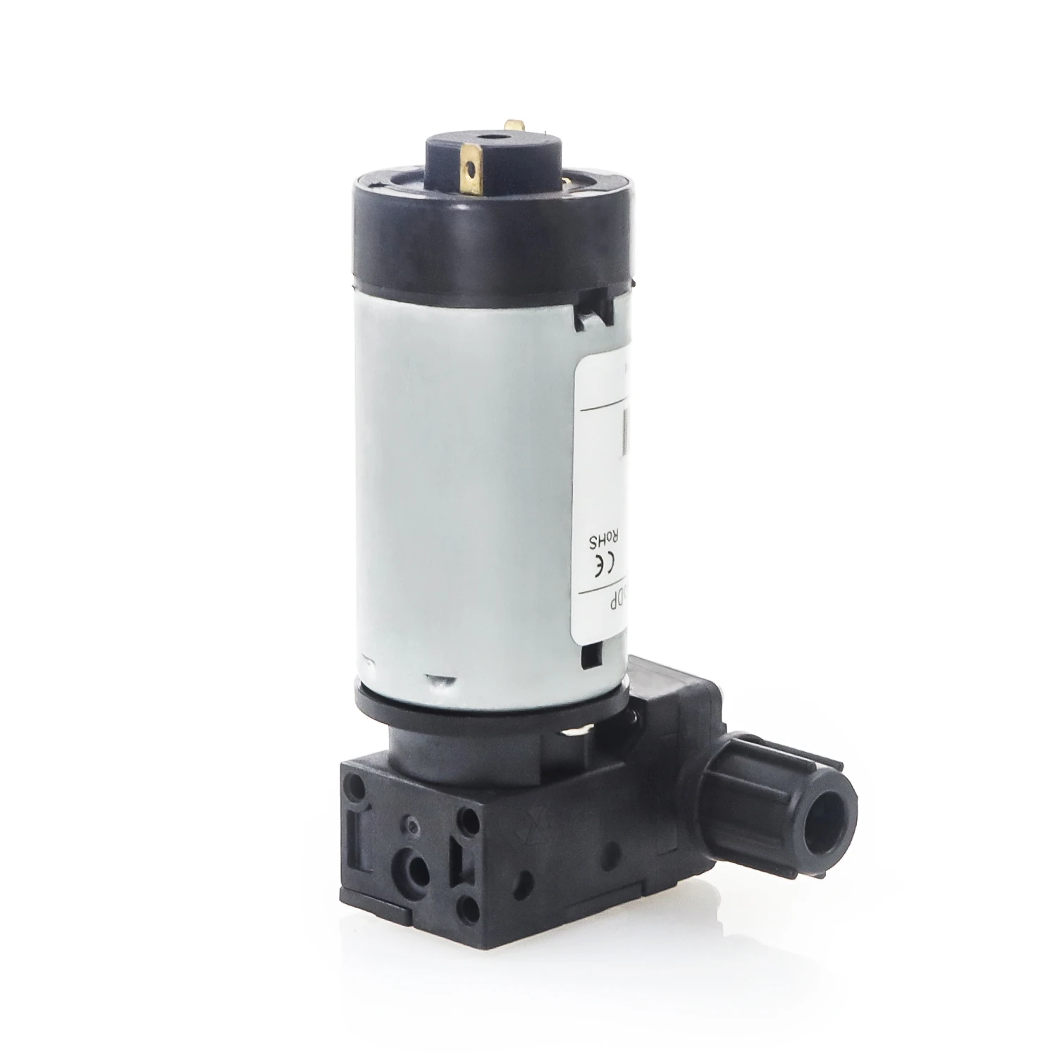
DPGL800 handles gas or gas–liquid aspiration permitted by its specific configuration. Check inlet gas content, foam, peak inflow and container vacuum; use a separately suitable solution for continuous liquid-only transfer.

02Define liquid-supply and aerated-aspiration branches separately

Suitable liquid diaphragm-pump configurations supply wash heads, stations or working vessels. Gas–liquid diaphragm pumps serve permitted aerated aspiration or related container-vacuum architectures. Describe actual inlet medium and gas–liquid state first, then determine pump position, incoming source and discharge destination.

Further technical reading

  • What Are Cleaning, Wash and Rinse Pumps in IVD Systems, and Why Are Miniature Diaphragm Pumps Used?
  • How to Read a Diaphragm Pump Flow-Pressure Curve—and Predict Installed Flow
  • IVD Waste Aspiration: Liquid Pump or Vacuum Pump? Direct vs Indirect Aspiration

03Match supply/removal capacity to washing-station and container conditions

Installed flow depends jointly on pump, tubing, valves, wash head and container; free flow does not directly represent station delivery. Evaluate supply by effective coverage and available time, and waste removal by peak inflow, lift, permitted residual liquid and full-container state. Check the complete wash cycle when supply and aspiration must be coordinated.

04Translate actual branch conditions into configuration requirements

Diaphragm-pump configuration conditions in hematology analyzers
ConditionTo confirm
Inlet mediumDistinguish liquid-only flow, intermittent gas entrainment and foam, and confirm the aspiration modes permitted by the configuration.
Tubing and containersProvide suction lift, outlet load, tubing and waste-container conditions.
Actual supply and removalMeasure incoming liquid, residue and emptying at the station; check handling after full level, shortage or blockage.
Operations supported in this instrument
OperationSpecific operating conditions
Hematology-channel cleaning and waste removalWash-fluid formulation, volume/time, spray/aspiration geometry, air/foam and waste capacity

05Compare product configurations by the roles on this page

Configuration options for the product roles on this page
ProductConfiguration optionConditions to verify
DPL30 liquid diaphragm pumpLiquid supply or auxiliary circulationSelect by installed resistance, actual wash or working fluid and task window
DPL60 liquid diaphragm pumpLiquid supply or auxiliary circulationJudge by peak demand and installed operating point, not free flow alone
DPL30H high-backpressure liquid diaphragm pumpLiquid branches requiring higher backpressure capabilityCalculate pressure budget and actual flow first, then confirm interfaces and materials
DPGL800 gas–liquid diaphragm pumpSuitable gas–liquid aspiration or container-vacuum branchesConfirm inlet medium and waste architecture; not for continuous liquid-only transfer (100% liquid)
  • DPL30 liquid diaphragm pump

    DPL30 liquid diaphragm pump

    View Details
  • DPL60 liquid diaphragm pump

    DPL60 liquid diaphragm pump

    View Details
  • DPL30H high-backpressure liquid diaphragm pump

    DPL30H high-backpressure liquid diaphragm pump

    View Details
  • DPGL800 gas–liquid diaphragm pump

    DPGL800 gas–liquid diaphragm pump

    View Details

06Explore specific operating and validation tasks

Hematology-channel cleaning and waste removal

Cleaning must cover sampling, reaction and detection branches; waste removal must handle simultaneous inflow. After restart, check blanks and channel state before resuming sample measurement.

  • Hematology-channel cleaning and waste removal

07Confirm product roles in actual operation

Operating-point validation and fault localization
OperationMeasurements and observationsPriority checks
Hematology-channel cleaning and waste removalConfirm supply and peak waste-removal capacity under installed resistance; measure residual liquid, carryover or assay-specified recoveryInsufficient supply, foam, dry aspiration and a full waste container disrupt the cleaning cycle

Check sampling, ratios and channel recovery with actual whole-blood conditions, and validate supply stability during continuous testing.

08Do similar nominal supply- and waste-pump flow rates make a matched pair?

Compare peak inflow, effective aspiration and permissible accumulation in the actual installation. The branches may handle different media and operating windows; validate station recovery over the complete sequence.

Metered dilution and sheath-fluid flow are different roles; sheath-fluid requirements depend on the detection architecture.

References

View references (5)
  1. [1]FOREACH DPL30 liquid diaphragm pump: configurations and specifications
  2. [2]FOREACH DPL60 liquid diaphragm pump: configurations and specifications
  3. [3]FOREACH DPL30H high-backpressure liquid diaphragm pump: configurations and specifications
  4. [4]FOREACH DPGL800 gas–liquid diaphragm pump: configurations and specifications
  5. [5]Sysmex hematology analyzer reference: impedance and fluorescence flow-cytometry configurations

Related guides

  • Back to the hematology analyzer fluidics overview
  • Hematology-channel cleaning and waste removal

Related Products

DPL30 Liquid diaphragm pumps

DPL30 Liquid diaphragm pumps

DPL60 Liquid diaphragm pumps

DPL60 Liquid diaphragm pumps

DPL30H High-backpressure liquid diaphragm pumps

DPL30H High-backpressure liquid diaphragm pumps

DPGL800 Gas–liquid diaphragm pumps

DPGL800 Gas–liquid diaphragm pumps

Related Technical Articles

What Are Cleaning, Wash and Rinse Pumps in IVD Systems, and Why Are Miniature Diaphragm Pumps Used?

Cleaning pump, wash pump and rinse pump usually name different duties within an IVD cleaning sequence, not three fixed pump mechanisms. Selection starts with wash volume, cycle rate, line resistance, wetted materials, and whether the duty is liquid supply or waste aspiration.

2026-09-03View Details

How to Read a Diaphragm Pump Flow-Pressure Curve—and Predict Installed Flow

A catalogue value such as 300 or 600 mL/min is not a fixed flow rate inside an instrument. The useful engineering question is: at the actual inlet pressure, outlet backpressure, fluid, tubing and supply voltage, where will the pump and the fluidic circuit settle?

2026-07-28View Details

IVD Waste Aspiration: Liquid Pump or Vacuum Pump? Direct vs Indirect Aspiration

Probe washing, reaction-cup cleaning, and routine waste removal in IVD instruments are all described as “waste aspiration.” Yet whether waste passes directly through a liquid pump or first enters a collection bottle while a vacuum pump creates negative pressure leads to entirely different selection logic.

2026-08-09View Details

Discuss Your IVD Fluidic Requirements

Share the instrument type, sample and reagent properties, working volumes, cycle timing, fluid path and acceptance criteria so we can discuss suitable components and prototype evaluation.

Discuss your application