Foreach TechnologyForeach Technology
Home
Products
Applications
About Us
Contact & Partnership
简体中文EnglishEspañolFrançais한국어Русский
Home
Products
Pump SeriesValve SeriesTubing SeriesFitting SeriesProbe SeriesSmart Control SeriesTubing Assemblies
Applications
All applicationsIVD DiagnosticsLife SciencesLaboratory AutomationAnalytical InstrumentsEnvironmental MonitoringSynthetic Biology
Resources
DatasheetsFluid Resistance CalculatorFitting ReplacementInstallation GuidesMaterial CompatibilityTechnical ArticlesCompany News
About Us
About ForeachR&D and ManufacturingQuality System and QualificationsMilestonesForeach Culture
Contact & Partnership
Contact UsBecome a Distributor
  • Pump Series
  • Valve Series
  • Probe Series
  • Fitting Series
  • Tubing Series
  • Control Series
  • Tubing Assemblies
  • All applications
  • IVD
  • Life Science
  • Lab Automation
  • Analytical Instruments
  • Environmental Monitoring
  • Synthetic Biology
  • Datasheets
  • Fluid Resistance Calculator
  • Fitting Replacement
  • Installation Guides
  • Material Compatibility
  • Technical Articles
  • Company News
  • About Foreach
  • R&D & Manufacturing
  • Quality & Compliance
  • History
  • Foreach Culture
  • Inquiry Form
  • Contact Information

Shenzhen Foreach Technology Co., Ltd.

Address: 13th Floor, 2nd Building, Yufengda Industrial Park, 1008th Guang Qiao Boulevard, Guangming District, Shenzhen 518132 CHINAView Map

Email: [email protected]

Tel: +86 755 8655 3831

LinkedInYouTubeFacebookInstagramX

© 2026 Shenzhen Foreach Technology Co., Ltd. All rights reserved.

Privacy Policy·

Home/Applications/In Vitro Diagnostics/Hematology analyzer
< Back

Bubble and pressure sensing in hematology analyzers

Application guide

Whole-blood aspiration, dilution and detection-channel supply produce different normal fluidic states. Monitoring in a hematology analyzer must be tied to the active channel and sample condition so a viscosity change, air entry or interrupted supply is not treated as the same event.

Applicable architecture

Hematology analyzers may use different detection principles and channel configurations. Diluent, lysing reagent and sheath-fluid locations depend on the specific method; sheath-flow conditions do not apply to every counting channel.[3]

Application guide

Hematology analyzer

Hematology analyzer
Diaphragm pumps in hematology analyzers
Hematology-channel cleaning and waste removal
Bubble and pressure sensing in hematology analyzers
Tubing and fittings in hematology analyzers
Multiport rotary valves in hematology analyzers
Detection-channel switching and fluid renewal
Piston pumps in hematology analyzers
Whole-blood sampling and delivery
Sampling probes in hematology analyzers
Syringe pumps in hematology analyzers
Diluent and reaction-reagent metering

On this page

What do these products do in this instrument?Build baselines for the blood-sampling and reagent branches separatelyConnect the affected sample to channel recoveryTranslate actual branch conditions into configuration requirementsState identificationCompare product configurations by the roles on this pageRelated operations and architecture comparisonsConfirm product roles in actual operationCan one pressure threshold identify a blood clot?ReferencesRelated guides

01What do these products do in this instrument?

Bubble and pressure sensing: distinguish air aspiration, bubbles and blockage

Acquire pressure or bubble information where the sample or supporting liquid actually passes. Keep aspiration, dilution and detection-supply observations distinct, including the detection architecture used by the instrument. The controller uses these records to investigate a fault; a pressure change alone does not diagnose a clot.

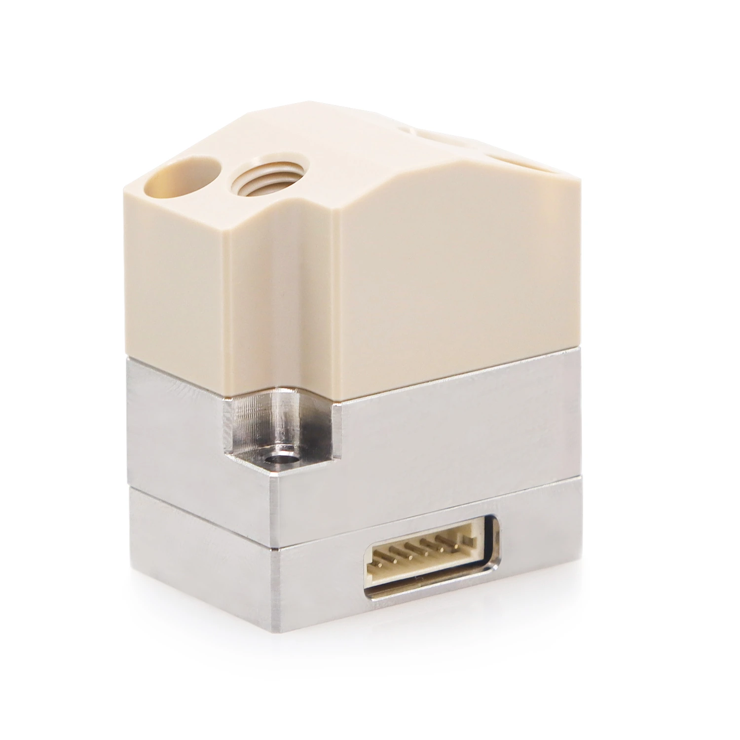
ABD provides bubble or liquid-state signals for defined tubing; PDM5 provides pressure information at a defined location. Configure module, position and action window separately; the controller associates affected samples or tasks.

02Build baselines for the blood-sampling and reagent branches separately

The sampling branch should be evaluated with method-permitted whole blood, its mixing state and the interval before aspiration. Reagent and detection-supply branches have different media and loads. Establish observations for each actual pump and valve phase rather than carrying a water-only sampling baseline into blood handling or a metered-dilution rule into continuous supply.

Further technical reading

  • Why Do Air Bubbles Delay or Bias Piston Pump Dispensing?
  • What is flow resistance calculation for? Using the Foreach calculator in fluid-path design and selection

03Connect the affected sample to channel recovery

An interruption before sample transfer is different from one after dilution or during detection. Preserve the sample identity, preparation stage and channel in use. Restore the fluid path, then check channel renewal and the method-required blank before deciding which sample result must be repeated or withheld under the analyzer procedure.

04Translate actual branch conditions into configuration requirements

Bubble- and pressure-sensing configuration conditions in hematology analyzers
ConditionTo confirm
Blood aspirationInclude mixing state, remaining sample volume, probe position and elapsed handling time in the sampling baseline.
Channel supplyIdentify the actual diluent, lysing reagent or method-required sheath branch and its operating phase; do not assume all counting channels use sheath flow.
Recovery evidenceRecord sample identity, dilution stage, affected channel, renewal sequence and blank result alongside the pressure or bubble event.
Operations supported in this instrument
OperationSpecific operating conditions
State identificationActual whole-blood handling and channel architecture, sampling versus supply phases, liquid-specific baselines, sample/preparation identity and required channel recovery

05State identification

During aspiration, relate the trace to the mixed specimen and remaining source volume. If delivery changes, review probe position and air entry together with the pressure event before repeating the sample operation.

During detection supply, distinguish a transient valve transition from sustained loss of the required liquid condition. Use the specific channel sequence to establish the observation and recovery windows.

Include repeated specimens and routine cleaning in verification. A baseline that works for one specimen or a clean line may misclassify normal variation or miss a progressively restricted path.

After clearing an affected branch, inspect renewal and the channel blank before returning to sample measurement. Record which sample stages were completed so a restart does not silently reuse a partially processed preparation.

06Compare product configurations by the roles on this page

Configuration options for the product roles on this page
ProductConfiguration optionConditions to verify
ABD bubble-detection moduleBubble or liquid-state identification in defined tubingValidate detection and false alarms for tubing material, dimensions, medium and action window
PDM5 pressure-detection modulePressure-state monitoring at a defined fluidic locationConfirm range and wetted configuration by model; validate normal baseline and abnormalities separately
  • ABD bubble-detection module

    ABD bubble-detection module

    View Details
  • PDM5 pressure-detection module

    PDM5 pressure-detection module

    View Details

07Related operations and architecture comparisons

Whole-blood sampling and delivery

Sample condition may change between repeated aspirations. Compare containers with normal remaining sample volume, low remaining sample volume and particle risks, recording tip position and air-aspiration handling rather than testing only repeated water aspiration/dispensing.

  • Whole-blood sampling and delivery

08Confirm product roles in actual operation

Operating-point validation and fault localization
OperationMeasurements and observationsPriority checks
State identificationCompare normal and challenged aspiration with representative permitted blood conditions, then exercise the relevant channel-supply faults. Record false alarms, missed events and recovery observations separately for each branch.Air, source depletion, sample changes and a restriction may produce overlapping observations. Check the active path and sample state before assigning a cause or accepting a channel result.

Verify that the alarm identifies a useful investigation window and that channel renewal restores the method-required conditions. Keep sample-delivery, dilution-ratio and detection-result checks as separate evidence.

09Can one pressure threshold identify a blood clot?

A threshold may flag a departure from the established baseline. Its cause still depends on sample condition, probe and valve state, liquid level and the measured location; investigate these conditions before deciding the sample and channel response.

Metered dilution and sheath-fluid flow are different roles; sheath-fluid requirements depend on the detection architecture.

References

View references (3)
  1. [1]FOREACH ABD bubble-detection module: configurations and specifications
  2. [2]FOREACH PDM5 pressure-detection module: configurations and specifications
  3. [3]Sysmex hematology analyzer reference: impedance and fluorescence flow-cytometry configurations

Related guides

  • Back to the hematology analyzer fluidics overview

Related Products

ABD Air-bubble detectors

ABD Air-bubble detectors

PDM5 Pressure sensors

PDM5 Pressure sensors

Related Technical Articles

Why Do Air Bubbles Delay or Bias Piston Pump Dispensing?

A completed piston stroke does not prove that the intended liquid volume reached the vessel. Bubble compression temporarily stores displacement; expansion can then cause a trailing dispense or affect the next cycle. Locate where bubbles first appear and compare synchronized pressure and individual dispense masses before and after priming.

2026-09-10View Details

What is flow resistance calculation for? Using the Foreach calculator in fluid-path design and selection

The free flow rate of the pump meets the requirements. After installing the pipelines, valves and joints, the liquid supply at the end is insufficient. Flow resistance calculations can break the problem down into comparable data: what pressure differential is required at the target flow rate, where does the pressure loss mainly occur, and what happens if the pipe diameter, pipe length, component Cv or medium viscosity is changed. This article combines the actual function of the Foreach flow resistance calculator with a recalculable fluid circuit case to explain how to use the calculation results for design, selection, troubleshooting and prototype verification.

2026-09-11View Details

Discuss Your IVD Fluidic Requirements

Share the instrument type, sample and reagent properties, working volumes, cycle timing, fluid path and acceptance criteria so we can discuss suitable components and prototype evaluation.

Discuss your application