
Miniature Diaphragm Pump Backflow After Stopping: Check Valves and Anti-Siphon Design
Diagnose reverse flow after a miniature diaphragm pump stops, distinguish it from forward siphoning and residual dripping, and evaluate check-valve behavior, valve sequencing and static sealing in the complete circuit.
For apparent backflow after stopping, first confirm that liquid really moves upstream and identify the reverse pressure difference. Then decide whether an additional check valve is needed. Continuing flow in the original direction calls for gravity-flow or siphon checks; brief dripping also requires residual-pressure and endpoint-volume checks.
Direction, duration and driving pressure determine the response. Adding an ordinary check valve to every stop-related problem may be ineffective and introduce resistance or starting difficulties.
Stopping the motor does not remove pressure or stored liquid
Motor stop ends active pumping. Height differences, reservoir pressure, compressed gas and elastic deformation do not immediately disappear. Liquid stored by a pressurized hose or damping element can continue toward the outlet.
The pump-head valves direct intake and discharge; they are not automatically validated shutoff valves. Without specified static sealing, opening pressure and leakage, the presence of check valves does not establish tight isolation at rest. Evaluate cracking pressure, forward-flow capability and closed-state internal leakage separately; one property cannot stand in for the others.
DPL30, DPL60 and DPL30H specifications provide operating and material information, but do not establish a forward free-flow threshold, reverse static leakage rate or post-stop volume over a defined interval sufficient to promise shutoff behavior. Define and test these in the instrument. [F1–F3]
Distinguish reverse flow, forward siphoning and dripping
| Observation | Possible mechanism | Useful distinction |
|---|---|---|
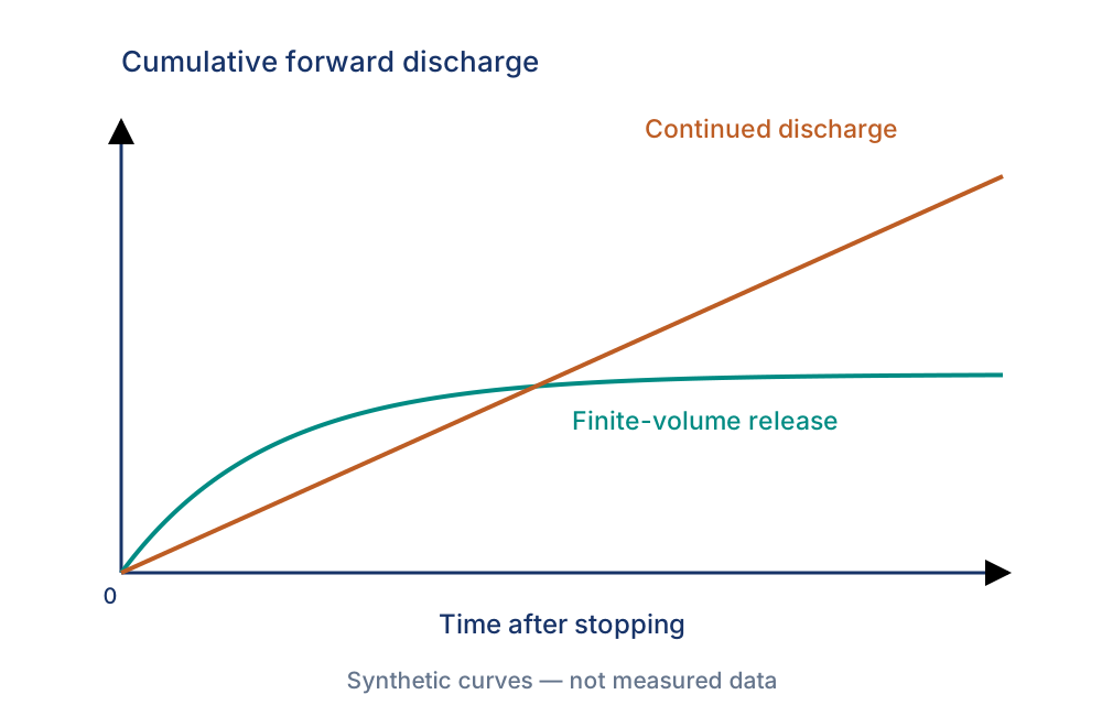
| Brief dripping that stops | Endpoint liquid, hose recovery, damper or gas pressure release | Outlet pressure falls and cumulative extra volume approaches a plateau |
| Continued flow in the original direction | Height or vessel pressure drives flow, possibly a siphon | Flow changes when level or pressure changes |
| Liquid moves toward the source reservoir | Downstream pressure, reverse gravity head or valve leakage | Record reverse flow and pressure; exclude elastic redistribution |
| A few drops detach at the nozzle | Wetting, surface tension and retained liquid | Upstream pressure is stable and liquid comes mainly from the end section |
These are diagnostic categories, not proof of a particular failure. Short tail discharge can have several sources. A small backward displacement may redistribute elastic volume and must not automatically be counted as reverse leakage through the pump.
Why an ordinary check valve may not stop forward siphoning
With sufficient upstream head or pressure and a continuous liquid column, flow may continue in the pumping direction after the motor stops. Where tubing crosses a high point and discharges lower down, assess siphon continuity, pressure at the high point and trapped gas.
For an illustrative water circuit with both ends at atmospheric pressure and a free discharge, a source surface 0.5 m above the outlet provides approximately 4.9 kPa static driving pressure. This uses density approximately 1000 kg/m³ and gravity approximately 9.81 m/s² before subtracting losses. It is not a Foreach opening-pressure or sealing specification. With a submerged outlet, use the receiving free-surface level and the two headspace pressures instead.
A check valve's free-flow direction commonly matches the pumping direction. If the remaining static pressure keeps it open, flow can persist. Assess reseating pressure, hysteresis, outlet-pressure effects and closed leakage as well as cracking pressure. One nominal opening value is insufficient.
Possible measures include reservoir/outlet repositioning, a suitable anti-siphon or backpressure device, or an actively controlled shutoff valve. For a spring-loaded backpressure or anti-siphon device, check opening and reseating conditions, preload settings and actual pressure drop at the required flow. Confirm fluid compatibility, pressure rating and connections for the complete circuit.
Treat residual dripping separately from reverse leakage
If cumulative discharge approaches a plateau, examine stop-time outlet pressure, hose compliance, gas volume, damping and the liquid between shutoff point and nozzle. Elastic tubing and compressed gas can store energy and release it after stopping. A damper added for pulsation control can therefore extend tail discharge.
A correctly closed check valve far upstream cannot retain all liquid already downstream of it. For strict endpoint dripping limits, assess shutoff closer to the outlet and valve-pump sequencing, including retained volume, cleaning and serviceability. Suck-back requires a circuit or actuator that actually supports it; a motor-direction input alone does not establish reversible liquid pumping.
For actual reverse flow, establish the pressure source before evaluating internal valve sealing and additional check measures. Particles, crystallization, chemical compatibility or long-term deformation may alter valve contact. Verify this with clean-condition, fluid and life-stage comparisons instead of blaming one material by default.
Recalculate the operating point before adding a valve
An added valve consumes pressure-difference capability. Use its pressure-drop curve at required flow and actual fluid, checking opening and closing conditions. If the curve already represents total open-valve pressure drop, do not add nominal cracking pressure again.
DPL30 and DPL60 specify 100 kPa rated pressure and DPL30H specifies 600 kPa. These values cannot be paired with no-load flow as simultaneous performance. [F1–F3] After adding a backpressure device, read or measure flow at the target pressure and repeat first-priming and minimum-level tests.
Coordinate valve and pump commands. Closing a downstream valve while the pump keeps running can rapidly increase outlet pressure. Limit abnormal deadheading and provide pressure protection as required by the system. Its limit depends on the lowest permissible pressure in the complete circuit, not only the pump rating. Also assess residual pressure and temperature changes in liquid trapped between two closed elements.
Include the stopped state in validation
Use the actual endpoint geometry. Reach the defined operating condition, then trigger stopping and recording from the same control event. Retain outlet pressure, supply or enable signal, valve command and collected post-stop volume. Reverse-flow tests need a suitable bidirectional instrument or a defined, cross-checked liquid-column volume method.
| Test | Conditions to cover | Output |
|---|---|---|
| Forward free flow | Highest source level, lowest outlet, vessel pressure boundaries | Continued flow and driving pressure difference |
| Tail discharge | Different operating backpressures, tubing and dampers | Cumulative volume versus time and stopping time |
| Reverse sealing | Plausible low and higher reverse pressures | Reverse volume during the specified idle interval |
| Restart | Short stops, normal waits and long idle periods | Priming recovery, bubbles and first-cycle volume |
| After endurance | Actual fluid, cleaning and required life stages | Changes in leakage, tail volume and starting |
Allow short pressure and volume redistribution to settle before interpreting persistent leakage. If counting drops, calibrate drop volume or use weighing, since fluid and nozzle changes affect drop size. Time windows and permissible tail and reverse volumes come from instrument requirements, not an undefined anti-backflow claim.
Define the required stopped-state function for Foreach selection
Provide reservoir and outlet positions, whether vessels are sealed, stopped backpressure, endpoint valves and nozzle, longest wait and allowable tail and reverse volume alongside normal flow requirements. Standard pump data defines candidate models; verify stop control with the actual valves, tubing and sequence.
If the instrument requires isolation when stopped, assign that function to a suitably validated component or system arrangement. This avoids treating pump-head valves as proven shutoff devices or adding resistance without solving the endpoint problem.
Specifications and references
Product parameters in this article come from the Foreach specifications below. Verify engineering explanations and proposed tests for the exact model and actual operating conditions.
[F1] Foreach DPL30 Chinese specification (A04)pp. 5–6: performance and configuration; pp. 3–4: mounting
[F2] Foreach DPL60 Chinese specification (A02)pp. 5–6: performance and configuration; pp. 3–4: mounting
[F3] Foreach DPL30H Chinese specification (A00)pp. 5–6: performance and configuration; pp. 3–4: mounting
Related selection and validation guides
Frequently asked questions
Can one check valve prevent both siphoning and backflow?
Not necessarily. Check valves normally restrict reverse flow. Forward flow also requires a check of the driving head, opening and reseating conditions.
Will switching to DPL30H reduce dripping after stopping?
Higher pressure capability does not establish better static sealing. Diagnose the liquid source, then assess pressure rating, valves and tubing.
Does a small tail volume mean the pump has failed?
No. Endpoint liquid and system pressure release can both produce it. Judge the volume within a defined time window against the application requirement.