
Selecting a Self-Priming Miniature Liquid Diaphragm Pump: Lift, Priming Time and Dry or Wet Starts
Select a self-priming miniature liquid diaphragm pump by checking suction lift, time to first liquid, dry and wet starting conditions, and stable delivery. Use DPL30, DPL60 and DPL30H specifications to define an instrument-level test.
An instrument may need to deliver cleaning liquid immediately after power-up. The reservoir is below the pump by less than the specified suction lift, yet the first cycle takes too long, replacing a bottle requires repeated starts, or bubbles remain at the endpoint after liquid leaves the pump.
Suction lift describes only one aspect of self-priming. R&D must also establish the initial condition of the chamber and tubing, whether displaced air can escape, when liquid first arrives and when the instrument receives stable flow. Evaluate these conditions alongside the actual operating flow of a Foreach DPL pump.
Turn self-priming into a measurable instrument requirement
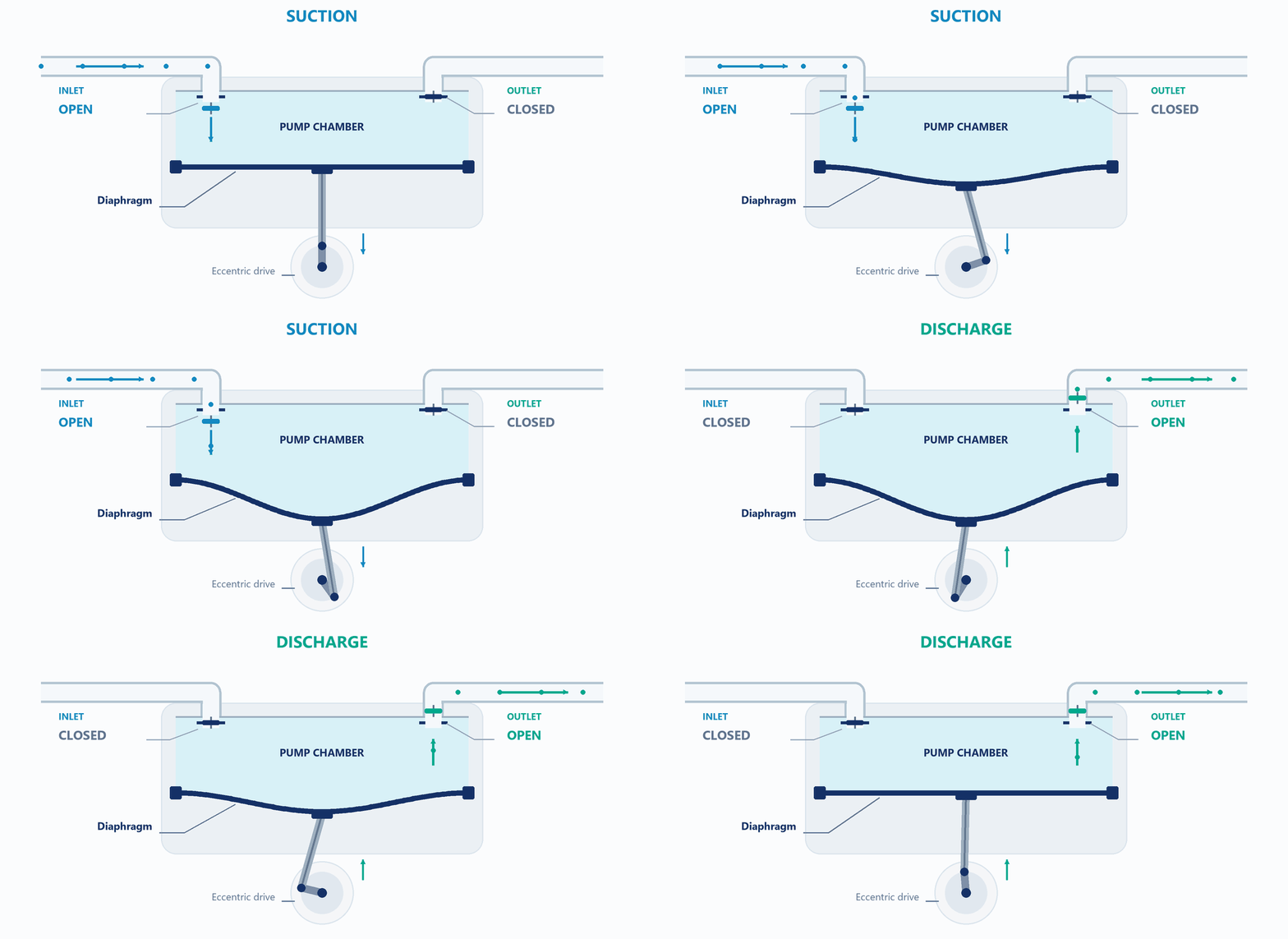
The diaphragm changes chamber volume while inlet and outlet valves direct intake and discharge. An initially empty suction line presents air first, then alternating gas and liquid, and finally a filled liquid path. Valve sealing, compressibility and effective displacement differ across these stages.
The ability to lift liquid and the ability to supply the endpoint within an allowed time require separate acceptance criteria.
| Metric | Suggested definition | Design question |
|---|---|---|
| Geometric suction height | Vertical difference between the lowest permitted reservoir level and pump inlet | What static suction burden does the installation add? |
| Time to first liquid | Effective start command to first liquid at a specified observation point | How long does initial filling or bottle replacement take? |
| Time to stable delivery | Start to endpoint flow and bubble state entering agreed limits | When may the instrument begin its next action? |
| Restart recovery | Repeated starts after defined idle time and residual-liquid condition | Can routine stop-start operation recover reliably? |
State the observation point explicitly. Liquid at the pump outlet does not prove that a downstream tube, valve chamber or wash needle has filled. Define allowable flow variation, observation duration and bubble criteria from the instrument task; one visible drop is insufficient.
Read the Foreach specifications as separate performance quantities
The following values come from page 5 of the respective Chinese specifications. They are separate specification items, not a simultaneous operating point. [F1–F3]
| Series | No-load flow | Rated pressure | Self-priming height | Standard connection |
|---|---|---|---|---|
| DPL30 | 300 mL/min | 100 kPa | 6 mH₂O | Hose with 3.2 mm internal diameter |
| DPL60 | 600 mL/min | 100 kPa | 3 mH₂O | Hose with 3.2 mm internal diameter |
| DPL30H | 300 mL/min | 600 kPa | 3 mH₂O | Compression fitting for 6 × 4 mm OD × ID rigid tubing |
A higher no-load flow does not automatically mean greater suction lift, and a higher outlet-pressure rating does not replace suction-side evaluation. Compare DPL60 for greater delivery capacity and DPL30H for higher outlet backpressure, then recheck minimum liquid level and starting conditions for either choice.
These specification tables do not define an associated time to first liquid, dry/wet starting state or complete test circuit. A 6 mH₂O value therefore cannot be rewritten as rapid self-priming from 6 m with any fluid and tubing, or used alone to predict instrument start-up time.
Why a larger tube may still prime slowly
Once filled, tube diameter, length and local restrictions determine part of the suction pressure loss. During priming, the volume of air to remove also matters. Increasing diameter may reduce liquid-flow resistance while increasing the volume to fill.
For a geometric example, a straight 1 m tube with 3.2 mm ID holds approximately 8.0 mL; at 4.0 mm ID it holds approximately 12.6 mL. These are calculated tube volumes, excluding fittings, valves and the pump chamber; they are not pump measurements.
Do not divide these volumes by the specified no-load liquid flow to estimate priming time. Air-handling capacity, valve sealing and outlet pressure participate in the starting process. Keep the suction line as short as practical and reduce unnecessary fittings and filling volume. If priming is difficult, check inlet leakage, blocked valves or filters, trapped air in the head and outlet pressure individually.
An open reservoir adds static burden as its level falls. A sealed reservoir also needs an air-admission assessment: withdrawal can lower headspace pressure even when the geometric height is unchanged. High points, valve chambers and fittings can retain different amounts of air on successive starts.
Test dry and wet starts separately
A wet start generally means that the chamber or critical valve surfaces are already wetted. For a dry start, define whether both the chamber and suction line are empty, how they are emptied and how the initial state is restored. Do not pool the results.
Wetting can affect valve contact, local gas paths and initial evacuation. A successful prefilled restart does not prove first-start performance after long storage. Test new or deliberately emptied units, short stops after operation, long idle periods and air entry during bottle replacement as distinct conditions.
Self-priming capability is not permission for unlimited dry running. Confirm allowable duration, duty cycle and temperature rise for the exact model and task. Repeated emptying or gas/liquid switching also warrants a gas-liquid application assessment. DPGL800 specifies gas and gas-liquid mixtures; its single-head 6 L/min no-load gas flow cannot be used to calculate a DPL liquid circuit's priming time. [F4]
Use controlled comparisons to locate the bottleneck
Start with the specified purified water, short tubing, low suction height and a leak-tight baseline. Add the actual system progressively, changing one main variable at a time. Retain model, wetted-material combination, supply and initial wetting state. Record inlet and outlet pressure, voltage at the pump, first-liquid and stable-delivery times, and bubble locations.
| Comparison | Observe | Investigate |
|---|---|---|
| Short baseline versus actual suction line | Priming time and inlet pressure | Resistance, fill volume or leakage |
| Normal versus minimum reservoir level | Delayed or unstable endpoint delivery | Static burden and suction margin |
| Low-backpressure versus actual outlet | Empty-line starting behavior | Air escape, valve state and starting backpressure |
| Prefilled versus defined empty condition | First-start and restart differences | Wetting, trapped air and initial state |
| Purified water versus actual fluid | Time, pressure and bubbles | Viscosity, gas release and compatibility |
Measurement ports add volume and possible leaks; leak-check them after installation. Use components compatible with the fluid and pressure. Do not pursue limiting values by prolonged deadheading or arbitrarily extended dry running.
Record vacuum development separately from successful liquid arrival. Rotation or falling inlet pressure shows that a process is occurring; it does not establish that liquid has reached the specified point.
What the selection record should establish
At minimum liquid level, specified temperature and actual outlet conditions, identify the model and material configuration that completes priming, the variation between starts and any required valve sequence or prefilling. Use the project's sample count, repeat count and life-stage requirements; one successful start of one new pump cannot establish production acceptance.
For a Foreach DPL30, DPL60 or DPL30H assessment, provide reservoir height, circuit volume and resistance, target flow, outlet backpressure, fluid formulation, initial dry/wet state and permitted waiting time.
Specifications and references
Product parameters in this article come from the Foreach specifications below. Verify engineering explanations and proposed tests for the exact model and actual operating conditions.
[F1] Foreach DPL30 Chinese specification (A04)pp. 5–6: performance and configuration; pp. 3–4: mounting
[F2] Foreach DPL60 Chinese specification (A02)pp. 5–6: performance and configuration; pp. 3–4: mounting
[F3] Foreach DPL30H Chinese specification (A00)pp. 5–6: performance and configuration; pp. 3–4: mounting
[F4] Foreach DPGL800 Chinese specification (A00)pp. 5–6: performance and configuration; pp. 3–4: mounting
Related selection and validation guides
Frequently asked questions
Does DPL30's higher suction lift mean it always starts more easily than DPL60?
No. Priming time also depends on circuit volume, valve condition, fluid and actual backpressure. Compare them from the same initial state.
Does successful operation after prefilling prove that the pump is suitable?
It helps diagnose the problem, but confirm whether the instrument permits prefilling and whether new, aged and bottle-change starts meet the task.
Is suction testing unnecessary when the installed height is below the specified lift?
No. Height alone excludes inlet leakage, tubing losses, reservoir air admission and the path for displaced air.